台达DVP-10PM可编程控制器安装教程:电气与安全指南
需积分: 17 89 浏览量
更新于2024-07-16
收藏 835KB PDF 举报
台达可编程控制器(PLC)DVP-10PM安装说明提供了关键的安装和安全指南。首先,这份说明书着重于电气规格和功能描述,强调了编程和指令信息不在其范围内,用户需参考《DVP-PM应用手册:编程篇》获取这些详细内容。对于选配的外围装置,如特殊模块,建议查阅产品随附的手册或《DVP-PLC应用手册:特殊模块篇》以获取完整的信息。
DVP-10PM是一个开放型设备,安装时应确保在无尘、低湿度、无电击和振动的环境下进行,以防止非专业人员意外操作导致设备损坏。在安装过程中,必须避免将输入交流电源直接连接到I/O端子,因为这可能导致严重的设备损坏。在接线前务必仔细检查,确保接地端正确连接,以防电磁干扰。
产品特性与尺寸部分提供了具体的数据,可能包括设备的外形尺寸、接口布局以及安装所需的硬件条件。图例可能包含示意图或组件布局,帮助用户理解和安装过程。此外,由于是英文版的说明,所以操作者需要具备一定的英语阅读能力,如果对英语不熟悉,可能需要借助翻译工具或找懂行的人员协助。
安全措施是安装过程中不可忽视的部分,因为错误的操作可能会对设备本身和使用者造成危害。遵循说明书中的步骤,并在必要时寻求专业指导,确保安装过程顺利且符合安全规定。在整个安装过程中,始终将预防性维护和合规操作放在首位。DVP-10PM的安装不仅涉及到硬件配置,还包括了系统集成、编程和环境适应性等方面,是一个综合性的工程任务。
- 3 -
#1:X0, X2, X4 and X6 can separately be the DOG signal for X, Y, Z and A axes. X1, X3, X5
and X7 can be the PG0 signal for the four axes
#2:X10、X11 are MPG pulse inputs.
#3:X12、X12 and X13 can only receive differential pulse signals for counting.
Output Points
Single common port transistor
Spec.
Items
Two differential outputs
High speed
Max. frequency
1 MHz 200 kHz
Output indicator LED display; light on = ON, light off = OFF
Output point configuration
Y10 to Y17
#1
Y0 to Y3
#2
Working voltage 5 VDC 5 to 30 VDC
Max. output current 40 mA 40 mA
Insulation
Line driver Photocoupler isolation
Resistive
< 25 mA
0.5A/1 point (4 A/COM)
Inductive
--
12 W (24 VDC)
Maximum load
Lamp
--
2 W (24 VDC)
OffOn
Max. output
response time
OnOff
0.2 μs 0.2 μs
Over-current protection N/A
#1:Y10+,Y10-,Y12+,Y12-,Y14+,Y14-,Y16+,Y16-:Forward-running pulse output;
Pulse/direction: Pulse output; A/B phase output: A phase
Y11+,Y11-,Y13+,Y13-,Y15+,Y15-,Y17+,Y17-: Reverse-running pulse output; Pulse
direction: Direction output; A/B phase: output: B phase
#2:Y0 to Y3 are 4 groups of PWM outputs; and can be the independent outputs.
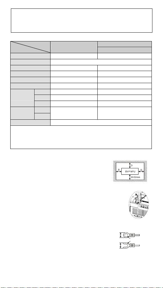
Installation
Please install the PLC in an enclosure with sufficient space
around it to allow heat dissipation.
Direct Mounting: Please use M4 screw according to the
dimensions of the product.
DIN Rail Mounting: When mounting the PLC to a 35mm DIN rail, be sure to use the
retaining clip to stop any side-to-side movement of the PLC and
reduce the chance of wires being loosened. The retaining clip is at
the bottom of the PLC. To secure the PLC to the DIN rail, pull down
the clip, place it onto the rail and gently push it up. To remove the
PLC, pull the retaining clip down with a flat screwdriver and gently
remove the PLC from the rail
Wiring
1. Use the O-type or Y-type terminal. See the figure in the
right hand side for the specifications. The PLC terminal
screws should be tightened to 9.50 kg-cm (8.25 in-Ibs)
and use only 60/75ºC copper conductors.
To s uit M3 . 5
screw terminals
Below
6.2 mm
Below
6.2 mm
2. DO NOT wire empty terminals, or place the input signal cable and output power
cable in the same wiring circuit.
3. DO NOT drop tiny metallic conductors into the PLC while screwing and wiring. Tear
off the sticker on the heat dissipation hole to prevent alien substances from
dropping in to ensure normal heat dissipation of the PLC.
剩余15页未读,继续阅读
213 浏览量
460 浏览量
251 浏览量
2024-10-30 上传
2024-10-30 上传
2024-10-30 上传
2024-11-08 上传
2024-10-30 上传


