68013 Slave FIFO传输与寄存器配置详解
需积分: 10 151 浏览量
更新于2024-07-24
收藏 1.97MB DOC 举报
"68013 slave fifo 说明文档"
68013 Slave FIFO 是一种在 FPGA(Field-Programmable Gate Array)设计中用于数据传输的接口组件,主要在与外部设备如微控制器、处理器或其他FPGA进行通信时使用。这份说明文档详细介绍了68013 Slave FIFO的各种特性和操作方式。
FX2特性介绍:
FX2是该文档中可能涉及的一种特定的FPGA芯片或接口控制器,具有以下特性:
1.1 介绍:FX2是一款高度集成的USB接口芯片,提供了一种灵活的方法来实现USB设备功能。
1.2 结构:FX2包含一个8位微处理器和一个高速USB接口,以及内部RAM和多个I/O端口。
1.3 特征:它支持USB 2.0全速操作,具有强大的自定义I/O能力,能够轻松处理复杂的通信协议。
Slave FIFO传输:
2.1 概述:Slave FIFO是一个在FX2或类似架构中的缓冲区,允许主设备(如微控制器)与FPGA之间高效地进行数据交换。
2.2 硬件连接:Slave FIFO通过特定的I/O引脚与主设备连接,这些引脚用于控制数据的读写以及握手信号。
2.3 Slave FIFO的传输方式:
- 同步Slave FIFO写:主设备在收到FPGA的确认信号后才能写入新数据,确保数据正确传输。
- 同步Slave FIFO读:主设备在接收到数据并给出响应后,FPGA才清除内部数据,确保数据不丢失。
- 异步Slave FIFO写:主设备可以连续写入数据,无需等待FPGA的确认,适用于高数据速率传输。
- 异步Slave FIFO读:FPGA在准备好数据后立即通知主设备,主设备可以随时读取,提高了数据吞吐量。
寄存器设置:
3.1 IFCONFIG到3.13 PORTACFG,这部分详细列出了与配置和控制Slave FIFO相关的各种寄存器,包括它们的功能和用法:
- IFCONFIG:接口配置寄存器,用于设置Slave FIFO的工作模式和通信参数。
- PINFLAGSAB/CD:I/O引脚配置寄存器,定义了哪些引脚作为数据线,哪些作为控制信号。
- FIFORESET:FIFO复位寄存器,用于初始化或清除FIFO内部状态。
- FIFOPINPOLAR:FIFO引脚极性寄存器,定义了握手信号的高低电平含义。
- EPxCFG和EPxFIFOCFG:端点配置寄存器,用于配置Slave FIFO的读写端点和传输属性。
- EPxAUTOINLENH/L:自动输入长度寄存器,设定连续传输的数据包长度。
- EPxFIFOPFH/L:FIFO预填充寄存器,预先加载到FIFO的数据量。
- INPKTEND和OUTPKTEND:输入/输出包结束标志寄存器,指示数据包的结束。
- EPxFIFOIE和EPxFIFOIRQ:中断使能和中断请求寄存器,控制中断触发和处理。
- PORTACFG:端口A配置寄存器,用于配置与Slave FIFO相关的端口特性。
- EPxFIFOBCHEPxFIFOBCL:FIFO缓存和低级配置寄存器,用于优化数据传输的性能和效率。
通过理解和配置这些寄存器,用户可以根据具体应用需求定制Slave FIFO的行为,从而实现高效、可靠的USB通信。在实际设计中,需仔细阅读并遵循这些寄存器的使用指南,确保系统的稳定运行。
艾曼 FPGA 工作室 www.amfpga.cn
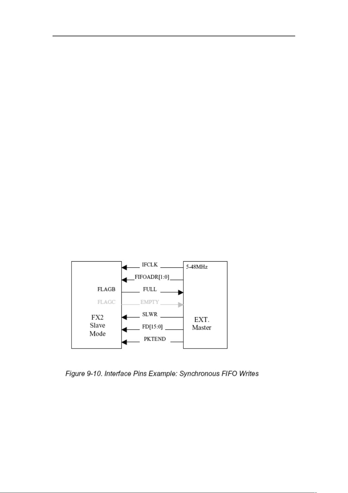
SLOE:FIFO 输出使能,外部逻辑控制,当 SLOE 无效时,数据线不输出有效数据;
SLRD:FIFO 读信号,外部逻辑控制,同步读时,FIFO 指针在 SLRD 有效时的每个
IFCLK 的上升沿递增,异步读时,FIFO 读指针在 SLRD 的每个有效—无效的跳变沿时递增;
SLWR:FIFO 写信号,外部逻辑控制,同步写时,在 SLWR 有效时的每个 IFCLK 的上
升沿时数据被写入,FIFO 指针递增,异步写时,在 SLWR 的每个有效—无效的跳变沿时数
据被写入,FIFO 写指针递增;
PKTEND:包结束信号,外部逻辑控制,在正常情况下,外部逻辑向 FX2 的 FIFO 中
写数,当写入 FIFO 端点的字节数等于 FX2 固件设定的包大小时,数据将自动被打成一包
进行传输,但有时外部逻辑可能需要传输一个字节数小于 FX2 固件设定的包大小的包,这
时,它只需在写入一定数目的字节后,声明此信号,此时 FX2 硬件不管外部逻辑写入了多
少字节,都自动将之打成一包进行传输;
FD[15:0]:数据线;
FIFOADR[1:0]:选择四个 FIFO 端点的地址线,外部逻辑控制。
2.3 Slave FIFO 的几种传输方式
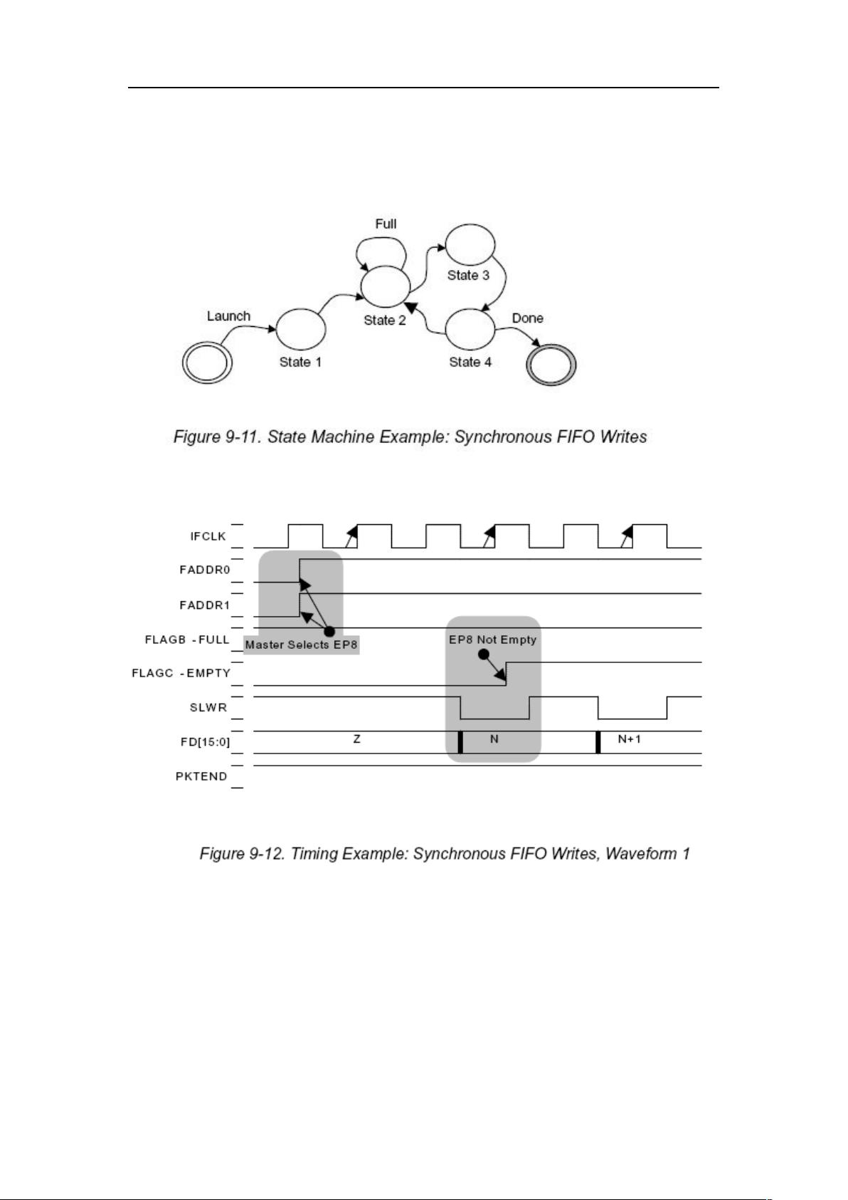
2.3.1 同步 Slave FIFO 写
同步 Slave FIFO 写的标准连接图如下:
同步 Slave FIFO 写的标准时序如下:
IDLE:当写事件发生时,进状态 1;
状态 1:使 FIFOADR[1:0]指向 IN FIFO,进状态 2;
状态 2:如 FIFO 满,在本状态等待,否则进状态 3;
7
剩余40页未读,继续阅读
2010-01-16 上传
2013-10-25 上传
2012-07-09 上传
2022-09-20 上传
点击了解资源详情
点击了解资源详情
点击了解资源详情
2021-10-20 上传
2022-09-20 上传

wzx1102k
- 粉丝: 3
- 资源: 4
 我的内容管理
展开
我的内容管理
展开


最新资源
- Angular实现MarcHayek简历展示应用教程
- Crossbow Spot最新更新 - 获取Chrome扩展新闻
- 量子管道网络优化与Python实现
- Debian系统中APT缓存维护工具的使用方法与实践
- Python模块AccessControl的Windows64位安装文件介绍
- 掌握最新*** Fisher资讯,使用Google Chrome扩展
- Ember应用程序开发流程与环境配置指南
- EZPCOpenSDK_v5.1.2_build***版本更新详情
- Postcode-Finder:利用JavaScript和Google Geocode API实现
- AWS商业交易监控器:航线行为分析与营销策略制定
- AccessControl-4.0b6压缩包详细使用教程
- Python编程实践与技巧汇总
- 使用Sikuli和Python打造颜色求解器项目
- .Net基础视频教程:掌握GDI绘图技术
- 深入理解数据结构与JavaScript实践项目
- 双子座在线裁判系统:提高编程竞赛效率
