硬件描述语言入门:Verilog与VHDL
发布时间: 2024-03-01 22:35:29 阅读量: 21 订阅数: 18 
# 1. 硬件描述语言概述
## 1.1 硬件描述语言简介
在数字电路设计和硬件工程中,硬件描述语言(Hardware Description Language,HDL)是一种用于描述电子系统硬件结构和行为的语言。HDL可以描述电路的功能、时序、结构和布局,是数字电路设计的重要工具。常见的硬件描述语言包括Verilog和VHDL。
## 1.2 硬件描述语言的作用与应用领域
硬件描述语言主要用于数字电路设计、仿真和综合,可以在不同抽象级别上进行电路的描述和设计。它在集成电路(IC)设计、传统的数字电路设计、FPGA设计、以及硬件/软件协同设计中都有广泛的应用。
## 1.3 Verilog与VHDL的发展历史
Verilog最早是由Gateway Design Automation公司于1984年开发,后被Cadence Design Systems公司收购。而VHDL是由美国国防部为了解决集成电路设计中的互操作性问题而开发的。它们分别代表了两种不同的硬件描述语言设计风格,分别基于C语言和Ada语言。这两种语言都在工业界得到了广泛的应用和支持。
# 2. Verilog基础入门
Verilog是一种硬件描述语言,用于描述数字电路的行为和结构。在本章中,我们将介绍Verilog的基础知识,包括语法、结构、模块和端口描述,以及组合逻辑和时序逻辑的应用。
### 2.1 Verilog的基本语法与结构
Verilog的基本语法类似于C语言,包括模块声明、数据类型、运算符等。以下是一个简单的Verilog模块示例:
```verilog
module example(input A, input B, output Y);
assign Y = A & B;
endmodule
```
在这个示例中,定义了一个模块名为"example",包含两个输入端口A和B,一个输出端口Y,实现了逻辑与操作。
### 2.2 Verilog模块与端口描述
Verilog中的模块是最基本的组织单元,用于描述数字电路的功能和结构。模块可以有输入和输出端口,用于与其他模块进行数据交换。以下示例展示了一个简单的Verilog模块和端口描述:
```verilog
module and_gate(input A, input B, output Y);
assign Y = A & B;
endmodule
```
在这个示例中,定义了一个与门模块"and_gate",包含两个输入端口A和B,一个输出端口Y,用于实现逻辑与操作。
### 2.3 Verilog中的组合逻辑与时序逻辑
Verilog可以描述数字电路中的组合逻辑和时序逻辑。组合逻辑是指电路中的门电路,根据输入立即产生输出;时序逻辑是指电路中带有时钟信号的部分,根据时钟信号进行操作。下面是一个简单的组合逻辑和时序逻辑的示例:
```verilog
// 组合逻辑
module comb_logic(input A, input B, input C, output Y);
assign Y = A & B | C;
endmodule
// 时序逻辑
module seq_logic(input clk, input D, output Q);
reg Q;
always @(posedge clk)
Q <= D;
endmodule
```
在这个示例中,"comb_logic"模块实现了与或操作的组合逻辑,"seq_logic"模块实现了时钟上升沿触发的时序逻辑。这些示例演示了Verilog中组合逻辑和时序逻辑的应用。
# 3. VHDL基础入门
VHDL(VHSIC Hardware Description Language,非常高速集成电路硬件描述语言)是一种硬件描述语言,广泛应用于数字电路设计和仿真中。本章将介绍VHDL的基础知识,包括语法结构、模块描述、组合逻辑和时序逻辑等内容。
#### 3.1 VHDL的基本语法与结构
VHDL的基本结构包括实体(entity)、架构(architecture)和过程(process)。实体定义了模块的接口,架构定义了模块的行为,过程描述了模块中的具体操作。
```vhdl
-- 实体定义
entity my_entity is
port (
input1: in std_logic;
input2: in std_logic;
output1: out std_logic
);
end entity my_entity;
-- 架构定义
architecture behavior of my_entity is
begin
-- 过程描述
process(input1, input2)
begin
if input1 = '1' and input2 = '1' then
output1 <= '1';
else
output1 <= '0';
end if;
end process;
end architecture behavior;
```
在上面的示例中,定义了一个名为`my_entity`的实体,包含两个输入端口和一个输出端口。在架构`behavior`中,使用`process`描述了基于输入端口进行的逻辑运算。
#### 3.2 VHDL模块与端口描述
VHDL支持模块化设计,可以通过实体来定义模块的接口和功能。端口描述定义了模块与外部环境的连接和通讯方式。
```vhdl
en
```
 最低0.47元/天 解锁专栏
 送3个月
 百万级
高质量VIP文章无限畅学
百万级
高质量VIP文章无限畅学
 千万级
优质资源任意下载
千万级
优质资源任意下载
 C知道
免费提问 ( 生成式Al产品 )
C知道
免费提问 ( 生成式Al产品 )
0
0
相关推荐

最低0.47元/天 解锁专栏
送3个月
百万级
高质量VIP文章无限畅学
千万级
优质资源任意下载
C知道
免费提问 ( 生成式Al产品 )
最新推荐
Python字典常见问题与解决方案:快速解决字典难题
# 1. Python字典简介
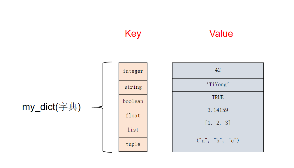
Python字典是一种无序的、可变的键值对集合。它使用键来唯一标识每个值,并且键和值都可以是任何数据类型。字典在Python中广泛用于存储和组织数据,因为它们提供了快速且高效的查找和插入操作。
在Python中,字典使用大括号 `{}` 来表示。键和值由冒号 `:` 分隔,键值对由逗号 `,` 分隔。例如,以下代码创建了一个包含键值对的字典:
```py
【实战演练】python个人作品集网站

# 2.1 HTML和CSS基础
### 2.1.1 HTML元素和结构
HTML(超文本标记语言)是用于创建网页内容的标记语言。它由一系列元素组成,这些元素定义了网页的结构和内容。HTML元素使用尖括号(<>)表示,例如 `<html>`、`<body>` 和 `<p>`。
每个HTML元素都有一个开始标签和一个结束标签,它们之间包含元素的内容。例如,一个段落元素由 `<p>` 开始标签
Python map函数在代码部署中的利器:自动化流程,提升运维效率

# 1. Python map 函数简介**
map 函数是一个内置的高阶函数,用于将一个函数应用于可迭代对象的每个元素,并返回一个包含转换后元素的新可迭代对象。其语法为:
```python
map(function, iterable)
```
其中,`function` 是要应用的函数,`iterable` 是要遍历的可迭代对象。map 函数通
Python Excel数据分析:统计建模与预测,揭示数据的未来趋势
# 1. Python Excel数据分析概述**
**1.1 Python Excel数据分析的优势**
Python是一种强大的编程语言,具有丰富的库和工具,使其成为Excel数据分析的理想选择。通过使用Python,数据分析人员可以自动化任务、处理大量数据并创建交互式可视化。
**1.2 Python Excel数据分析库**
numpy安装与性能优化:优化安装后的numpy性能

# 1. NumPy简介**
NumPy(Numerical Python)是一个用于科学计算的Python库。它提供了一个强大的N维数组对象,以及用于数组操作的高
OODB数据建模:设计灵活且可扩展的数据库,应对数据变化,游刃有余

# 1. OODB数据建模概述
对象-面向数据库(OODB)数据建模是一种数据建模方法,它将现实世界的实体和关系映射到数据库中。与关系数据建模不同,OODB数据建模将数据表示为对象,这些对象具有属性、方法和引用。这种方法更接近现实世界的表示,从而简化了复杂数据结构的建模。
OODB数据建模提供了几个关键优势,包括:
* **对象标识和引用完整性
Python列表操作的扩展之道:使用append()函数创建自定义列表类

# 1. Python列表操作基础
Python列表是一种可变有序的数据结构,用于存储同类型元素的集合。列表操作是Py
Python脚本调用与区块链:探索脚本调用在区块链技术中的潜力,让区块链技术更强大

# 1. Python脚本与区块链简介**
**1.1 Python脚本简介**
Python是一种高级编程语言,以其简洁、易读和广泛的库而闻名。它广泛用于各种领域,包括数据科学、机器学习和Web开发。
**1.2 区块链简介**
区块链是一种分布式账本技术,用于记录交易并防止篡改。它由一系列称为区块的数据块组成,每个区块都包含一组交易和指向前一个区块的哈希值。区块链的去中心化和不可变性使其
【实战演练】综合自动化测试项目:单元测试、功能测试、集成测试、性能测试的综合应用

# 2.1 单元测试框架的选择和使用
单元测试框架是用于编写、执行和报告单元测试的软件库。在选择单元测试框架时,需要考虑以下因素:
* **语言支持:**框架必须支持你正在使用的编程语言。
* **易用性:**框架应该易于学习和使用,以便团队成员可以轻松编写和维护测试用例。
* **功能性:**框架应该提供广泛的功能,包括断言、模拟和存根。
* **报告:**框架应该生成清
【进阶】FastAPI中的文件上传与处理

# 2.1 HTTP文件上传协议
HTTP文件上传协议是客户端和服务器之间传输文件的一种标准方式。它使用HTTP POST请求,并将文件作为请求正文的一部分发送。
**请求头:**
* `Content-Type`:指定请求正文的类型,通常为`multipart/form-data`。
资源上传下载、课程学习等过程中有任何疑问或建议,欢迎提出宝贵意见哦~我们会及时处理!
点击此处反馈


专栏目录

文章持续更新中,敬请期待~
最低0.47元/天 解锁专栏
送3个月
百万级
高质量VIP文章无限畅学
千万级
优质资源任意下载
C知道
免费提问 ( 生成式Al产品 )