Verilog HDL 2nd版:高级数字设计指南
需积分: 50 146 浏览量
更新于2024-07-17
3
收藏 135.36MB PDF 举报
"《Advanced Digital Design With the Verilog HDL 2nd》是关于Verilog HDL的高级数字电路设计图书,适用于IC设计工程师自我提升。本书基于IEEE 1464-1995标准的Verilog HDL,经过两次修订(IEEE 1364-2001和Verilog-2001/2005),旨在提高设计语言的效率和效果。"
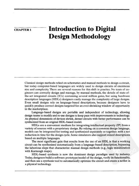
Verilog HDL是一种硬件描述语言,是现代应用特定集成电路(ASICs)设计的核心。通过使用HDL,设计师能够创建高阶、基于语言的电路抽象描述,并验证其功能和时序。这本书的第一版采用的是IEEE 1464-1995标准,但随着技术的发展,Verilog语言经历了两次重要的更新,即IEEE 1364-2001(Verilog-2001)和2005年的修订(Verilog-2005)。这些修订主要目的是改进语言的效率和有效性。
此书的第二版依然保持了与第一版相同的基本动机:帮助那些准备加入到产品设计团队的学生掌握如何在设计流程的关键阶段使用HDL。因此,它不仅仅覆盖了数字设计基础课程中的原则和方法,而是进一步深入,适合进阶学习。
自第一版以来,讨论HDL的书籍数量显著增加,大多数仍以基础教学为主。而《Advanced Digital Design With the Verilog HDL 2nd》则针对那些希望在数字设计领域更上一层楼的读者,提供了更全面和深入的指导。书中涵盖了Verilog HDL的高级行为建模,以及如何在设计流程的不同阶段应用这些模型来验证和优化集成电路设计。
本书的内容可能包括但不限于以下几个方面:
1. Verilog-2001和Verilog-2005的新特性与改进,如增强的语法、模块复用、综合友好性等。
2. 数字逻辑设计基础,包括基本门级电路、组合逻辑和时序逻辑的设计。
3. 高级设计技巧,如状态机建模、并行处理和接口设计。
4. 代码风格和最佳实践,以确保代码的可读性和可维护性。
5. 仿真与验证方法,包括基于测试平台的系统级验证。
6. 时序分析和时序约束的应用,以满足电路的性能要求。
7. 设计自动化工具的使用,如综合器、仿真器和形式验证工具。
通过阅读本书,读者可以深入了解Verilog HDL在现代数字系统设计中的应用,并提升其在IC设计领域的专业技能。无论是对于学术研究还是工业实践,这本书都是一本不可多得的参考资料。

11.8.3 JTAG Registers
798
11.8.4 JTAG Instructions
800
11
.8.5
TAP
Architecture 801
11
.8.6
TAP
ControllerStateMachin
e 803
1
1.
8.7 Design Example:Testing with JTAG
807
11.8.8 Design Example: Built-In Self-Test 830
References
845
Problems 845
A Verilog Primitives
851
A.I Multiinput Combinational Logic Gates 851
A.2 Multioutput Combinational
Gates
853
A.3 Three-State Logic
Ga
tes 854
A.4
MOS Transistot Switches 855
A.5
MOS Pull-Up/Pull-Down Gates 860
A.6
MOS Bidirectional Switches 860
B Verilog Keywords 863
C
Vcrilog Data Types 865
C.l Nets 865
C.2
Register Variables 866
C.3
Constants
870
C.4
Referencing Arra
ys
of
Nets
or
Regs 871
D Verilog Operators 873
0.1
Arithmetic Operators 873
0.2
Bitwise Operators
875
0.3
Reduction Operators 875
0.4
LogicalOperators
876
0.5 Relational Operators 877
0.6
Shift Operators 878
0.7
Conditional
Operator
878
0.8
Concatenation Operator
879
D.9 Expressions and
Ope
rands
880
0.10
Operator
Precedence
880
0.11 Arithmetic with Signed Data 'lYpes 881
0.12 Signed
Li
teral Integers 882
0.13
Syst
em
Functions for Sign Conversion
882
2.1.1 Assignment Width Extension 883
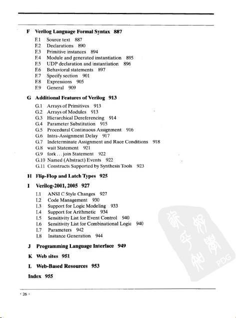
E Verilog Language Formal Syntax
88S
.".
剩余985页未读,继续阅读
178 浏览量
点击了解资源详情
点击了解资源详情
326 浏览量
233 浏览量
189 浏览量
103 浏览量
133 浏览量
2008-05-14 上传

pkwdpkwd
- 粉丝: 4
 我的内容管理
展开
我的内容管理
展开


最新资源
- Ruby语言集成Mandrill API的gem开发
- 开源嵌入式qt软键盘SYSZUXpinyin可移植源代码
- Kinect2.0实现高清面部特征精确对齐技术
- React与GitHub Jobs API整合的就业搜索应用
- MATLAB傅里叶变换函数应用实例分析
- 探索鼠标悬停特效的实现与应用
- 工行捷德U盾64位驱动程序安装指南
- Apache与Tomcat整合集群配置教程
- 成为JavaScript英雄:掌握be-the-hero-master技巧
- 深入实践Java编程珠玑:第13章源代码解析
- Proficy Maintenance Gateway软件:实时维护策略助力业务变革
- HTML5图片上传与编辑控件的实现
- RTDS环境下电网STATCOM模型的应用与分析
- 掌握Matlab下偏微分方程的有限元方法解析
- Aop原理与示例程序解读
- projete大语言项目登陆页面设计与实现
