IEC 61850-7-1:电力自动化通信基础结构
需积分: 10 164 浏览量
更新于2024-07-25
收藏 4.34MB PDF 举报
"IEC TC57 61850-7-1标准是电力自动化通信网络和系统的一部分,提供了电力设施如保护设备、断路器、变压器、变电站主机等之间的通信和交互的概述。这个标准是2011年的版本,旨在定义基本的通信结构、原则和模型。"
IEC TC57 61850-7-1是国际电工委员会(IEC)技术委员会57(TC57)制定的一项标准,它属于IEC 61850系列,主要关注电力系统自动化中的通信网络和系统。该标准的主要目的是促进电力公用事业自动化系统间的高效、可靠和互操作性的通信。
1. **基本通信结构**:
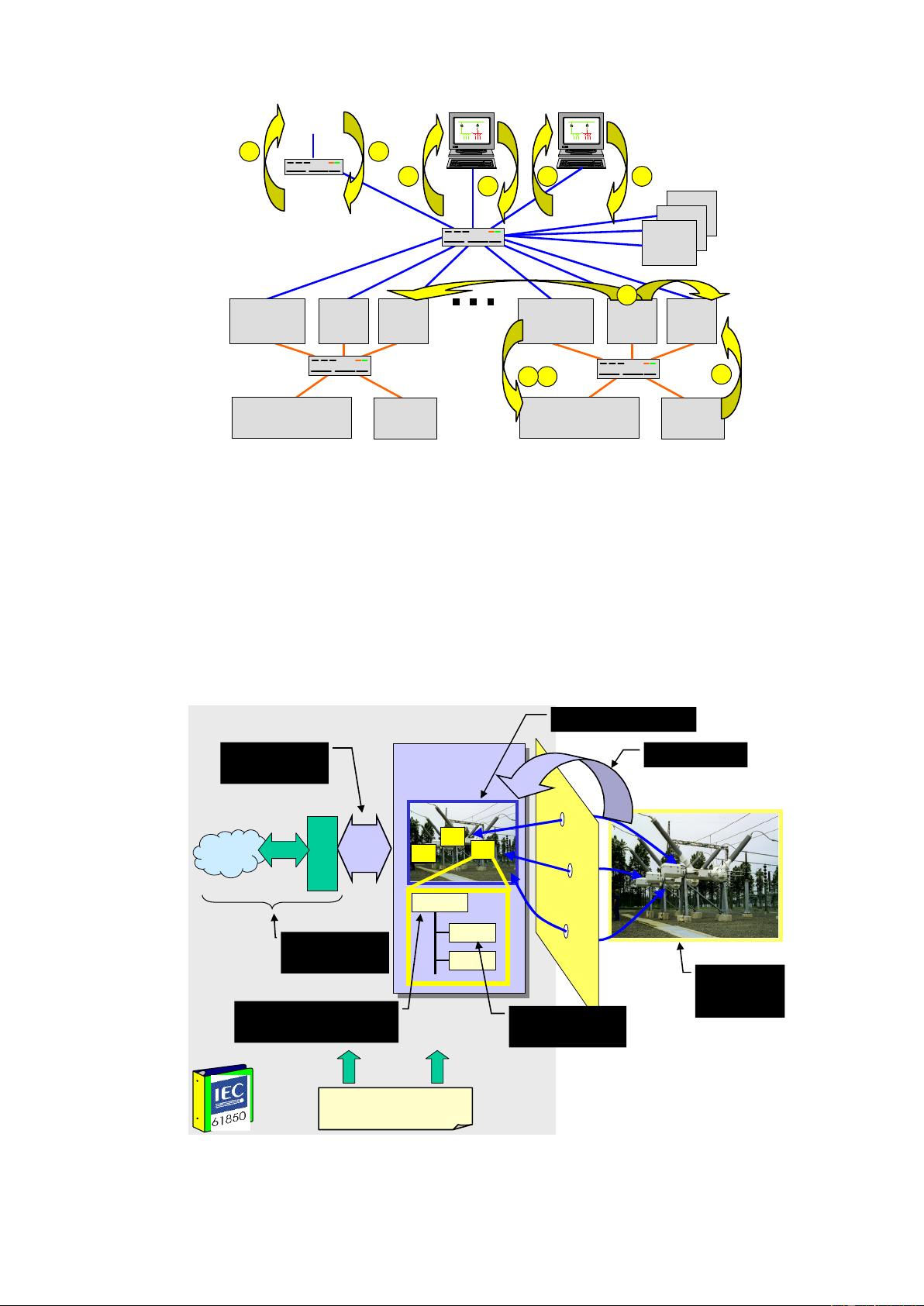
IEC 61850-7-1定义了电力自动化系统的基本通信架构,包括层次化的设计,使得不同级别的设备和系统能够有效地交换信息。这些层次可能包括过程层、间隔层和站控层,每个层都有特定的功能和通信需求。
2. **原则**:
- **标准化接口**:标准规定了设备间通信的标准接口,确保不同制造商的产品可以无缝集成。
- **面向服务的架构**:采用服务导向的方法,将功能封装为独立的服务,便于复用和组合。
- **数据模型**:定义了一套通用的数据模型,用于表示电力系统中的各种实体和变量,如电流、电压、状态信息等。
- **事件驱动**:通信基于事件,当系统状态发生变化时,自动触发信息交换。
3. **模型**:
- **逻辑节点和数据对象**:IEC 61850使用逻辑节点(LN)来代表变电站中的设备或功能,每个逻辑节点包含一组相关的数据对象(DO),这些对象代表设备的属性和测量值。
- **数据集(DA, LD, LN)**:数据集(Data Areas)包含逻辑设备(LD)、逻辑节点和数据对象,用于组织和管理通信。
- **MMS(制造报文规范)**:作为传输协议,MMS支持服务请求/响应机制,确保数据的可靠传输。
4. **应用**:
- **保护与控制**:标准有助于实现分布式保护和控制系统的通信,提高故障检测和恢复速度。
- **智能电网**:在智能电网中,61850-7-1标准帮助实现远程监控、自动化操作和能量管理。
- **维护与诊断**:提供实时状态信息,便于设备的维护和故障诊断。
5. **更新与替代**:
IEC 61850-7-1:2011版本取代了之前的2004年版本,反映了技术的进步和行业需求的变化,提升了标准的兼容性和适应性。
6. **实施与合规性**:
实施IEC 61850-7-1标准意味着设备必须符合其定义的通信规范,以确保在实际电力系统中的互操作性。这通常涉及到设备的软件升级和配置调整。
IEC TC57 61850-7-1标准对于电力系统自动化领域的通信标准化和互操作性至关重要,它为设计、安装和运行电力设施的自动化系统提供了统一的框架。理解和遵循这个标准是电力行业专业人员不可或缺的知识点。

DIN EN 61850-7-1:2012-04
EN 61850-7-1:2011
3.3
model
a representation of some aspect of reality
The purpose of creating a model is to help understand, describe, or predict how things work in the real world
by exploring a simplified representation of a particular entity or phenomenon. The focus of the model defined
in IEC 61850-7-x is on the communication features of the data and functions modelled.
4 Abbreviated terms
ACSI Abstract communication service interface
ASN.1 Abstract syntax notation one
API Application program interface
CDC Common data class
CT Current transformer
DST Daylight saving time
GOOSE Generic oriented object system event
IED Intelligent electronic device
LD Logical device
LN Logical node
LLN0 Logical node zero
LPHD Logical node physical device
MMS Manufacturing message specification
PHD Physical device
PICOM Piece of communication
SAS Substation automation system
SCSM Specific communication service mapping
SoE Sequence of events
SMV Sample values
UCAIug UCA international users group
UTC Universal time coordinated
VMD Virtual manufacturing device
VT Voltage transformer
XML extended markup language
5 Overview of the IEC 61850 series concepts
5.1 Objective
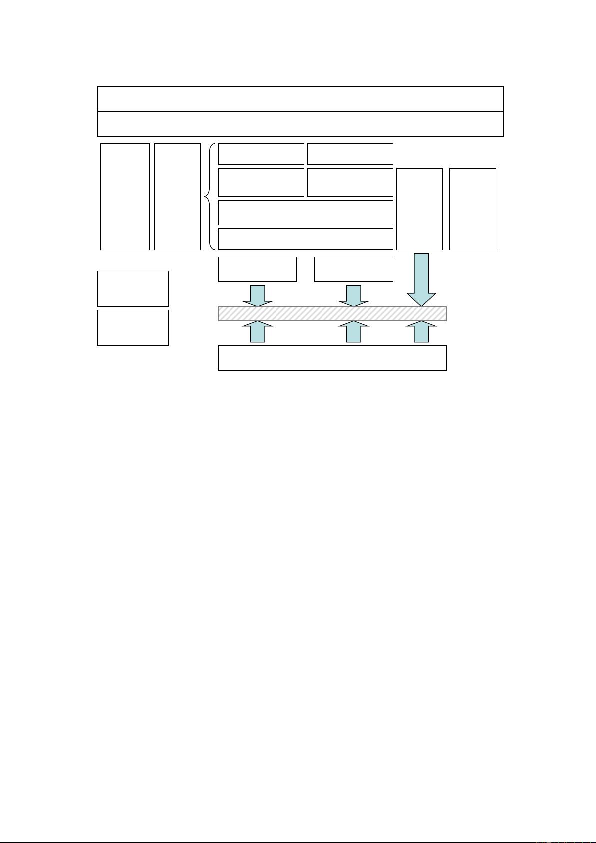
IEC 61850-7-4, IEC 61850-7-3, IEC 61850-7-2, IEC 61850-6, and IEC 61850-8-1 are closely related. This
subclause provides an overview of these parts and it describes how they are interwoven. The modelling and
implementation methods applied in the different parts of the standard and their relation are shown in Figure 1.
12
B55EB1B3E14C22109E918E8EA43EDB30F09DCCB7EF86D9
NormCD - Stand 2012-08


剩余131页未读,继续阅读
2023-07-29 上传
2023-07-27 上传
2023-12-19 上传
2023-06-06 上传
2023-12-02 上传
2023-05-15 上传
2023-06-03 上传
2023-05-16 上传
2023-09-18 上传

Abudoush
- 粉丝: 0
- 资源: 9
 我的内容管理
展开
我的内容管理
展开


最新资源
- C++多态实现机制详解:虚函数与早期绑定
- Java多线程与异常处理详解
- 校园导游系统:无向图实现最短路径探索
- SQL2005彻底删除指南:避免重装失败
- GTD时间管理法:提升效率与组织生活的关键
- Python进制转换全攻略:从10进制到16进制
- 商丘物流业区位优势探究:发展战略与机遇
- C语言实训:简单计算器程序设计
- Oracle SQL命令大全:用户管理、权限操作与查询
- Struts2配置详解与示例
- C#编程规范与最佳实践
- C语言面试常见问题解析
- 超声波测距技术详解:电路与程序设计
- 反激开关电源设计:UC3844与TL431优化稳压
- Cisco路由器配置全攻略
- SQLServer 2005 CTE递归教程:创建员工层级结构
