


PDP-11_40处理器手册:Unix V6开发的关键资源
下载需积分: 14 | PDF格式 | 6.66MB |
更新于2024-07-16
| 96 浏览量 | 举报
PDP-11_40处理器手册(1972)是一份由Digital Equipment Corporation (DEC) 出版的专业文档,它详细介绍了当时流行的PDP-11系列计算机系统的技术特性、架构和软件支持。该手册特别关注的是Unix V6开发所使用的PDP-11计算机,这在当时是一个重要的技术平台。
首先,手册在第一章“简介”中概述了PDP-11_40的主要特征。1.1节讨论了系统的通用特性,包括其高效能的UNIBUS总线系统,这是一种标准接口,允许不同硬件组件间的无缝通信。UNIBUS设计允许模块化扩展,增强了系统的灵活性。
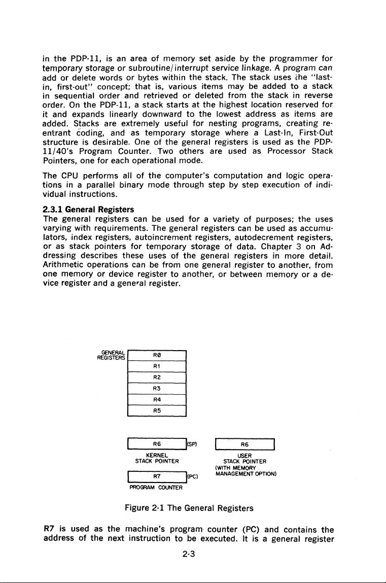
1.2节着重于中央处理器,介绍了它的基本结构,如寄存器体系、浮点运算能力和内存管理功能。处理器具有通用寄存器用于数据处理,同时提供处理器状态字,用于跟踪指令执行状态。栈限制寄存器则支持高效的堆栈操作。
在1.3节,手册探讨了外部设备和选项,涵盖了输入/输出设备(如纸带机和磁盘驱动器)以及不同类型的总线扩展选项,以适应多样化的应用场景需求。此外,1.4节涉及软件部分,提到了用于纸带输入的专用软件以及基于磁盘的操作系统软件,如Unix V6,这是当时的主流操作系统之一。同时,手册还介绍了高级编程语言的支持,以便开发人员编写更复杂的程序。
章节2“系统架构”进一步深入,2.1和2.2部分详细描述了系统架构,包括双向数据线设计和主从关系,确保了系统之间的可靠通信。中央处理器的详细内核结构在2.3节详述,包括核心寄存器和控制逻辑。此外,自动优先级中断系统在2.6.1节有所提及,强调了中断处理对于实时性和效率的重要性,以及如何有效地利用它们。
这份PDP-11_40处理器手册提供了关于70年代中期PDP-11系列计算机的核心技术信息,对于理解那个时代的计算机设计思想和技术实践具有重要意义。无论是硬件设计、系统通信、还是软件支持,都是那个时代信息技术发展的重要组成部分。
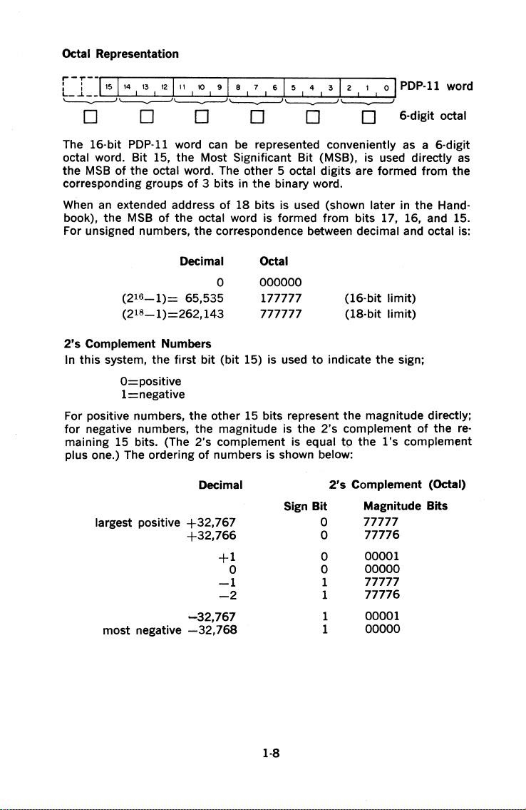
Octal Representation
:-:--1~5114
13
12l11
10
gl
e 1
&15
4 3 [ 2 1 o I
PDP-11
word
~~-------_!---)~~
I I
~~---------~
D D D D D D 6-digit octal
The 16-bit
PDP-11
word can
be
represented conveniently
as
a 6-digit
octal word. Bit 15, the Most Significant
Bit
(MSB), is used directly
as
the
MSB
of
the octal word. The other 5 octal digits are formed from
the
corresponding groups
of
3 bits in the binary word.
When
an
extended address
of
18 bits is used (shown later in the Hand-
book),
the
MSB
of
the octal word is formed from bits 17, 16, and 15.
For unsigned numbers, the correspondence between
decimal and octal is:
Decimal
0
(216-1)=
65,535
(218-1)=262,143
2's
Complement Numbers
Octal
000000
177777
777777
(16-bit
limit)
(18-bit
limit)
In
this
system, the
first
bit
(bit
15) is used
to
indicate
the
sign;
O=positive
1=negative
For positive numbers, the other 15 bits represent the magnitude directly;
for
negative numbers, the magnitude is
the
2's
complement
of
the
re-
maining 15 bits. (The
2's
complement is equal
tp
the
1's
complement
plus
one.) The ordering
of
numbers is shown below:
Decimal
2's
Complement (Octal)
Sign
Bit
Magnitude Bits
largest positive
+32,767
0
77777
+32,766
0
77776
+1
0
00001
0
0
00000
-1
1
77777
-2
1
77776
-32,767
1
00001
most negative
-32,768
1
00000
1-8
剩余211页未读,继续阅读
相关推荐


sygthk
- 粉丝: 0
 我的内容管理
展开
我的内容管理
展开


最新资源
- 宜华健康2021年上半年业绩及分析报告
- MPC8349微处理器手册:技术参考指南
- MATLAB语音识别技术开发与应用
- 单片机流量控制系统设计与实现
- PASV-JavaScript-Syntax深入解析
- 深入浅出:C语言中的冒泡排序算法
- 基于Android-Struts2-MySQL实现登录功能详解
- VB.net实现简易TCP/IP通讯实例教程
- 策联传媒2021年半年度报告深度解析
- Matlab实现虹膜识别技术研究
- WF第六章:实例源码加载与卸载技巧
- 单片机初学者必备:完整程序代码及电路图解析
- 探索Matlab开发:SunsetColormap的颜色艺术
- GPSS典型例题解析
- 毕业设计:基于协同过滤算法的电影推荐系统
- 易语言开发的桌面制作软件源码分享