TMC2130:高性能步进电机驱动芯片数据手册
下载需积分: 50 | PDF格式 | 2.82MB |
更新于2024-07-15
| 67 浏览量 | 举报
"TMC2130是一款专用于两相步进电机的高性能驱动集成电路,其数据手册提供了详细的驱动电路、寄存器配置和芯片特性。该芯片支持2.0A线圈电流(峰值2.5A),具备微步进插值功能、SPI接口,并能在4.75到46VDC的电压范围内工作。"
TMC2130芯片的特征和优势包括:
1. **2相步进电机驱动**:设计适用于最高2.0A的线圈电流,峰值可达2.5A,适合驱动各种类型的两相步进电机。
2. **微步进插值**:采用microPlyer技术,实现高分辨率的步进控制,最高可达256细分,确保平滑运动。
3. **SPI接口**:标准SPI接口简化了与微控制器之间的通信,提高了系统集成的灵活性。
4. **宽电压范围**:工作电压在4.75到46VDC之间,适应性强,能应对不同电源环境。
5. **stealthChop技术**:这是一种超静音运行和流畅运动的技术,大大降低了电机运行时的噪声。
6. **spreadCycle技术**:这种高度动态的电机控制斩波器,确保电机控制的高效和快速响应。
7. **dcStep负载依赖速度控制**:根据负载条件自动调整电机速度,提高系统性能。
8. **stallGuard2**:高精度无传感器电机负载检测,可识别电机是否卡死,提升系统的可靠性。
9. **coolStep节能电流控制**:通过智能电流控制,最多可节省75%的能源,降低系统运行成本。
10. **集成电流感应选项**:内置电流感测功能,能精确控制电机电流,确保稳定运行。
11. **被动刹车和自由轮模式**:在电机停止时提供被动刹车,且支持自由轮模式,防止电机惯性继续转动。
12. **全面保护和诊断**:包括过热、过流和短路保护等,保障设备安全运行。
13. **小型封装**:采用5x6mm² QFN36或TQFP48封装,节省板级空间,适用于紧凑型设计。
TMC2130芯片广泛应用在纺织机械、缝纫机、工厂及实验室自动化、3D打印机、液体处理、医疗设备、办公自动化、闭路电视、安防系统、自动取款机、现金循环器、销售点设备、泵和阀门等领域。
这款芯片结合了高效能、低噪音和智能控制技术,是驱动两相步进电机的理想选择。通过SPI接口和丰富的功能集,开发者可以轻松地实现精确、节能且安静的步进电机控制,满足各种应用需求。
TMC2130 DATASHEET (Rev. 1.10 / 2018-MAY-09) 16
www.trinamic.com
3.4.2 Internal Regulator Bridged
In case a clean external 5V supply is available, it can be used for complete supply of analog and
digital part (Figure 3.5). The circuit will benefit from a well-regulated supply, e.g. when using a +/-1%
regulator. A precise supply guarantees increased motor current precision, because the voltage at
5VOUT directly is the reference voltage for all internal units of the driver, especially for motor current
control. For best performance, the power supply should have low ripple to give a precise and stable
supply at 5VOUT pin with remaining ripple well below 5mV. Some switching regulators have a higher
remaining ripple, or different loads on the supply may cause lower frequency ripple. In this case,
increase capacity attached to 5VOUT. In case the external supply voltage has poor stability or low
frequency ripple, this would affect the precision of the motor current regulation as well as add
chopper noise.
5V Voltage
regulator
+5V
5VOUT
VSA
4.7µ
VCC
470n
10R
Well-regulated, stable
supply, better than +-5%
Figure 3.5 Using an external 5V supply to bypass internal regulator
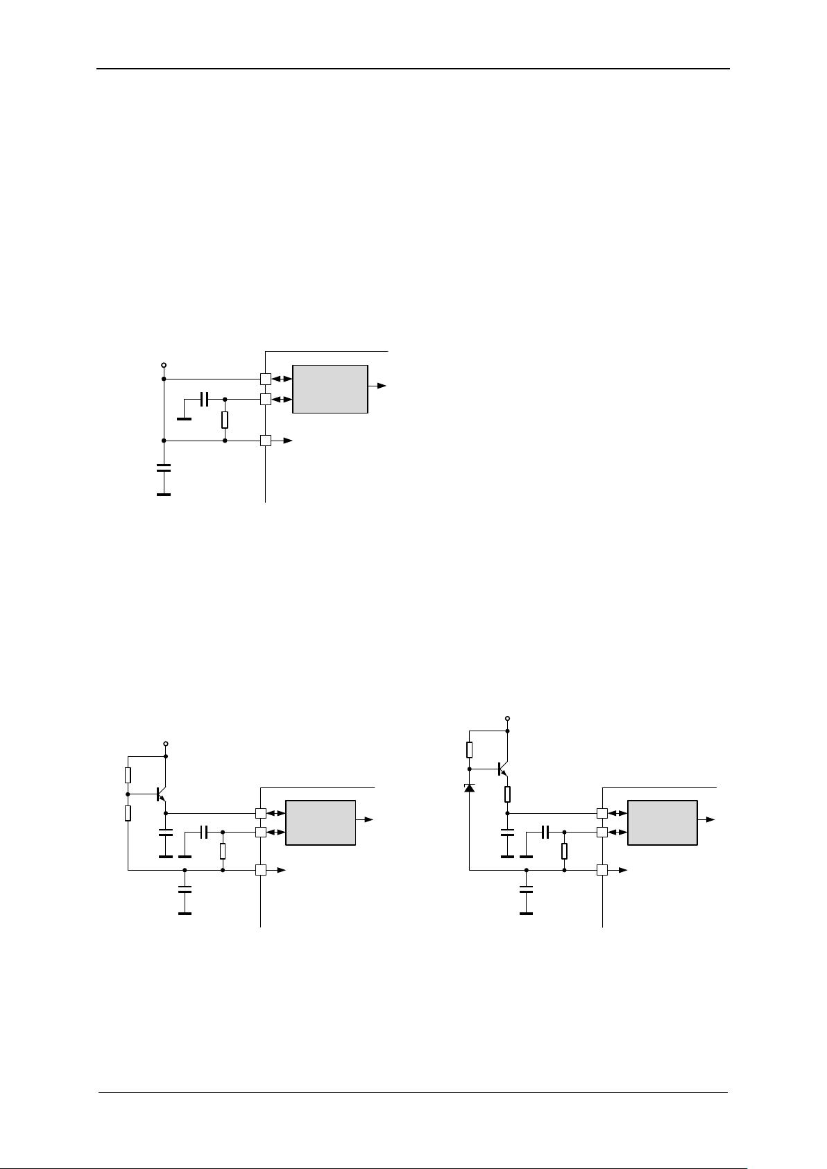
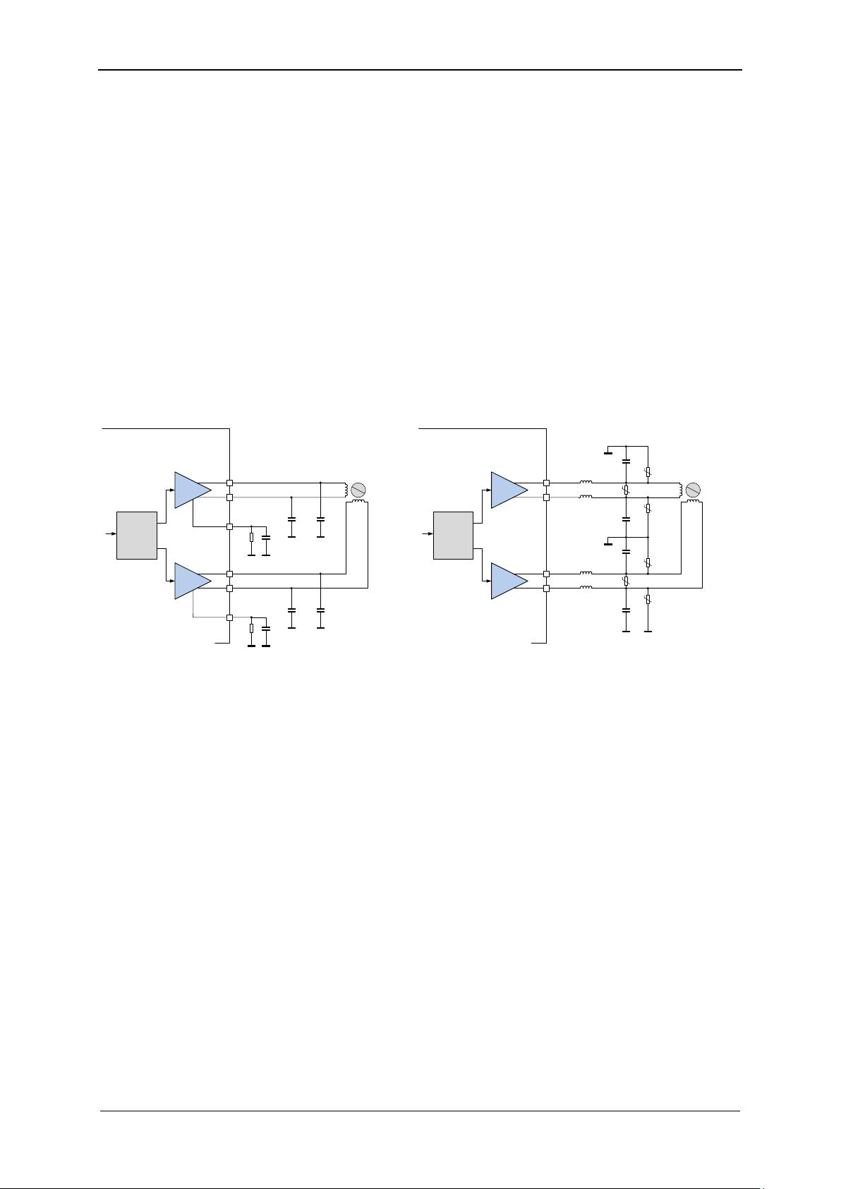
3.5 Pre-Regulator for Reduced Power Dissipation
When operating at supply voltages up to 46V for VS and VSA, the internal linear regulator will
contribute with up to 1W to the power dissipation of the driver. This will reduce the capability of the
chip to continuously drive high motor current, especially at high environment temperatures. When no
external power supply in the range 5V to 24V is available, an external pre-regulator can be built with
a few inexpensive components in order to dissipate most of the voltage drop in external components.
Figure 3.6 shows different examples. In case a well-defined supply voltage is available, a single 1W or
higher power Zener diode also does the job.
5V Voltage
regulator
5VOUT
VSA
4.7µ
VCC
470n
+V
M
2R2
BCX56 or
similar
22k
4k7
Simple pre-regulator for 24V up to 46V
5V Voltage
regulator
5VOUT
VSA
4.7µ
VCC
470n
+V
M
2R2
BCX56 or
similar
22k
Simple short circuit protected pre-regulator for 24V up to 46V
Z5.6V e.g.
MM5Z5V6
100R
470n
16V
470n
16V
Figure 3.6 Examples for simple pre-regulators
剩余102页未读,继续阅读
相关推荐


W17667164853
- 粉丝: 2
 我的内容管理
展开
我的内容管理
展开


最新资源
- 信息技术公司笔试面试题集锦
- 超声弹性图像处理:一种可变形网格运动追踪方法
- C++编程指南:高效与规范实践
- Div+CSS布局完全指南:从入门到精通
- 林斌博士揭示编写优质代码的十大关键策略
- 华为JAVA面试试题与解析
- 十天速成ASP.NET:从安装到调试环境
- 数缘社区:数学与密码学的宝库
- SAP初学者入门:操作手册与关键步骤
- Visual Studio 2005类库速查:核心类与命名空间详解
- Makefile入门:Linux编译流程与实践
- 数据流图绘制详解与实战
- 大规模分布式并行检索:技术概述与计算所的研究进展
- Linux设备驱动开发全指南:从入门到实战
- Macromedia Flash MX教程:构建动画与网页设计
- ARM44B0开发板实验配置与环境搭建指南
