解决非旋转对称问题:带圆柱补偿器的球面与双曲面_null测试方法
67 浏览量
更新于2024-08-29
收藏 437KB PDF 举报
本文主要探讨了在非旋转对称的圆柱补偿器辅助下的null测试方法应用于toroidal表面和biconic表面的测量问题。随着这两种光学表面在现代光学系统中的广泛应用,如光学设计中的光路补偿和光学元件制造,由于它们的非旋转对称性,传统的null测试技术往往难以准确地评估其形貌。为了解决这一难题,研究者提出了利用圆柱补偿器进行null测试的新策略。
首先,文章深入剖析了这种方法的理论基础。通过圆柱补偿器,能够创建一个局部旋转对称的参考框架,使得原本非对称的表面在该框架下表现出旋转对称性,从而简化了null测试的复杂性。这种补偿器能够补偿表面在不同轴向位置的形状差异,使得整个测试过程更加精确。
接着,作者详细分析了这种方法的误差来源。这些误差可能包括补偿器自身的精度、安装误差、环境因素(如温度变化)以及补偿器与被测表面间的接触精度。为了量化这些误差,文中可能涉及了误差模型的建立和实际测试结果的对比分析。
在实践部分,文章展示了三种典型的设计实例,这些光学测试系统都采用了圆柱补偿器。通过设计优化,作者得到了满意的测试结果,表明这种方法在实际应用中是可行的。设计结果不仅包含了补偿器的选择和配置,还包括了测量系统的总体布局和性能指标,如分辨率、灵敏度和稳定性等。
最后,研究给出了设计结果和总误差评估,这为其他工程师和研究人员提供了实施类似测试的实用指南。总的来看,这项工作对于提升非旋转对称表面的null测试效率和精度具有重要意义,为进一步优化光学设计和制造流程奠定了基础。
总结来说,这篇论文提供了一种创新的null测试方法,解决了toroidal表面和biconic表面的非对称性带来的测量难题,对于推动光学行业的精密测量技术发展具有积极影响。
COL 11(Suppl.), S22202(2013) CHINESE OPTICS LETTERS September 30, 2013
Null testing toroidal surface and biconic surface
with cylinder compensator
Zhuang Liu (
444
FFF
)
1,2
and Yan Gong (
ýýý
ñññ
)
1∗
1
State Key Laboratory of Applied Optics, Changchun Institute of Optics
§
Fine Mechanics
and Physics, Chinese Academy of Sciences, Changchun 130033, China
2
University of Chinese Academy of Sciences, Beijing 100049, China
∗
Corresponding author: gongy@sklao.ac.cn
Received July 11, 2013; accepted August 14, 2013; posted online September 25, 2013
Toroidal surface and biconic surface are employed increasingly, however their profile cannot be null tested
easily for they are non-rotationally symmetrical. Null testing method with cylinder compen sator is pro-
posed to solve this problem. The theory of this method is revealed. The errors of this method are present.
Three typical testing optical systems with cylinder compensator are demonstrated at last. The design
results and total error indicate that this method is feasible.
OCIS codes: 220.1000, 220.1250, 220.3620, 220.4840.
doi: 10.3788/COL201311.S22202.
Toroidal surface and biconic surface are increasingly used
in modern advanced optical instruments. The toroidal
surface which has different radii in sagittal and tangen-
tial plane can reduce effectively astigmatism and coma.
Thus it is employed widely in off-axis or multi-pass opti-
cal system. Biconic surface which has two more degrees
of freedom than toroidal surface can improve optical sys-
tem’s performance greatly. They will be widely used in
future.
The toroidal surface and biconic surface cannot be
tested directly by interferometer without any compen-
sators because they are non-rotationally symmetrical.
There are two common methods to test these types of
surfaces. One method is use o f profilometry. The surface
is measured one point or one line at a time by profilom-
etry, profile of the surface can be generated by mapping
out several hundred points or lines. This process is not
exp ensive, but it do es not offer the detail of an inter-
ferometric map. Precision of this method is several tens
of nanometers. Accuracy will degrades when table’s in-
stability increases due to long distance (in excess of a
couple inches). Ano ther option available is null testing
with computer generated holograms (CGH), figures can
be measur e d interferometrically. This metho d is the com-
monest method, but hologram required the customized
program for different surface s and lithography etching
on chrome made it time-consuming, laboring, and expen-
sive. One hologram canno t be used to different profiles
[1]
.
Cylinder surface is also non-rotatio nally symmetrical.
It is curving in one direction and flat in orthogonal di-
rections. As a compensator, cylinder lens can turn the
spherical wavefront from one point (the cat-eye) into non-
rotationally symmetrical wavefront which fits the tested
toroidal surface or biconic surfac e and take the place of
CGH in null testing. Compared with hologram, cylinder
lens can be got easily, and one cylinder le ns can be used
for different profiles.
Methods of null testing toroidal surface and biconic
surface with cylinder compensator are discussed in de-
tail. The compe nsation theor y of toroidal surface and bi-
conic surface is shown, and tolerance ana ly sis is covered
as well. Three null testing optical systems with cylinder
compensator for three typical surfaces are designed. De-
sign r esults demonstrate this method’s feasibility.
The curve of toroidal surface in the tangential plane is
defined by
Z =
y
2
R
1 +
q
1 −
y
2
R
2
. (1)
This curve is then rotated about an axis parallel to the
Y axis a nd intersecting the Z ax is with a distance ρ from
the vertex. Toroidal surface has 2 radii: radius R in sagit-
tal plane and rotate radius ρ in tangential plane. In most
cases, the toroidal s urface is concave. We se t the cylin-
der lens’ generatr ix perpendicular to the tangential plane
to correct the wavefront from the cat-eye, and discuss its
theory in sagittal plane and tangential plane respectively.
In sagittal plane, the cylinder can be considered as a
plane plate lens. The plane plate lens whose thickness
is not neglected will lead to the longitudinal displace-
ment and wavefront aberration. As a compensato r, the
primary aberratio n is 3rd-order spherical wavefront aber-
ration.
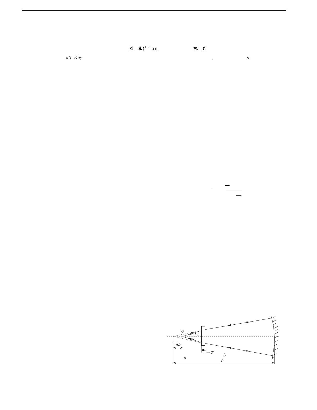
As shown in Fig. 1, the longitudinal displacement L
produced by passage through a plate of thickness T and
refractive index n is easily found by Snell’s law for small
angle of incidence to be
Fig. 1. Layout of compensation optical system in sagittal
plane.
1671-7694/2013/S22202(5) S22202-1
c
2013 Chinese Optics Letters
下载后可阅读完整内容,剩余4页未读,立即下载
2019-08-23 上传
2022-07-14 上传
2023-06-01 上传
2024-04-25 上传
2023-05-05 上传
2024-10-19 上传
2024-10-19 上传
2024-10-20 上传

weixin_38601390
- 粉丝: 4
- 资源: 910
 我的内容管理
展开
我的内容管理
展开


最新资源
- 天池大数据比赛:伪造人脸图像检测技术
- ADS1118数据手册中英文版合集
- Laravel 4/5包增强Eloquent模型本地化功能
- UCOSII 2.91版成功移植至STM8L平台
- 蓝色细线风格的PPT鱼骨图设计
- 基于Python的抖音舆情数据可视化分析系统
- C语言双人版游戏设计:别踩白块儿
- 创新色彩搭配的PPT鱼骨图设计展示
- SPICE公共代码库:综合资源管理
- 大气蓝灰配色PPT鱼骨图设计技巧
- 绿色风格四原因分析PPT鱼骨图设计
- 恺撒密码:古老而经典的替换加密技术解析
- C语言超市管理系统课程设计详细解析
- 深入分析:黑色因素的PPT鱼骨图应用
- 创新彩色圆点PPT鱼骨图制作与分析
- C语言课程设计:吃逗游戏源码分享
