没有合适的资源?快使用搜索试试~ 我知道了~
首页RS422&RS485的通信规约介绍
RS422&RS485的通信规约介绍

关于串口RS422,RS485的英文介绍,RS422是一种全双工通信方式,RS485属于半双工通信方式,适用于长距离传输
资源详情
资源评论
资源推荐

RS-422/485 Application Note Cover Page
B&B Electronics -- PO Box 1040 -- Ottawa, IL 61350
PH (815) 433-5100 -- FAX (815) 434-7094
RS-422 and RS-485
Application Note
B&B Electronics Mfg. Co. Inc.
P.O. Box 1040 -- Ottawa, IL 61350
PH (815) 433-5100 -- FAX (815) 434-7094
Internet Addresses:
B&B Home Page: http://www.bb-elec.com
Customer Service: sales@bb-elec.com
Technical Support: techsupt@bb-elec.com
B&B Electronics - Revised October 1997

RS-422/485 Application Note Table of Contents i
B&B Electronics -- PO Box 1040 -- Ottawa, IL 61350
PH (815) 433-5100 -- FAX (815) 434-7094
Table of Contents
CHAPTER 1: OVERVIEW ...........................................................................1
INTRODUCTION.............................................................................................1
DATA TRANSMISSION SIGNALS ......................................................................1
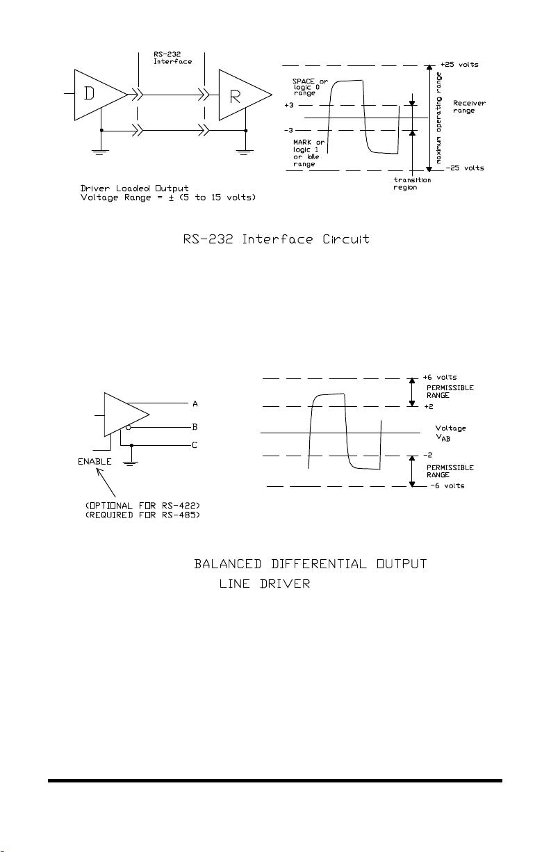
Unbalanced Line Drivers.........................................................................1
Balanced Line Drivers .............................................................................1
Balanced Line Receivers..........................................................................3
EIA STANDARD RS-422 DATA TRANSMISSION ..............................................3
EIA STANDARD RS-485 DATA TRANSMISSION ..............................................6
TRISTATE CONTROL OF AN RS-485 DEVICE USING RTS..................................9
SEND DATA CONTROL OF AN RS-485 DEVICE ..............................................11
CHAPTER 2: SYSTEM CONFIGURATION ............................................13
NETWORK TOPOLOGIES............................................................................... 13
TWO WIRE OR FOUR WIRE SYSTEMS............................................................13
TERMINATION.............................................................................................16
BIASING AN RS-485 NETWORK....................................................................17
EXTENDING THE SPECIFICATION .................................................................. 19
CHAPTER 3: SELECTING RS-422 AND RS-485 CABLING ..................20
NUMBER OF CONDUCTORS ..........................................................................20
SHIELDING .................................................................................................20
CABLE CHARACTERISTICS ........................................................................... 20
CHAPTER 4: TRANSIENT PROTECTION OF RS-422 AND RS-485
SYSTEMS.................................................................................................... 23
WHAT DOES A SURGE LOOK LIKE? ................................................................23
Surge Specifications............................................................................... 23
Common Mode vs. Differential Mode.....................................................25
GROUND ≠ GROUND....................................................................................26
TRANSIENT PROTECTION USING ISOLATION ..................................................27
Isolation Theory.....................................................................................27
Isolation Devices ................................................................................... 28
TRANSIENT PROTECTION USING SHUNTING ..................................................28
Shunting Theory.....................................................................................28
Connecting Signal Grounds ................................................................... 29
Shunting Devices ................................................................................... 29
COMBINING ISOLATION AND SHUNTING .......................................................29
SPECIAL CONSIDERATION FOR FAULT CONDITIONS.......................................31
CHOOSING THE RIGHT PROTECTION FOR YOUR SYSTEM ................................. 31

ii Table of Contents RS-422/485 Application Note
B&B Electronics -- PO Box 1040 -- Ottawa, IL 61350
PH (815) 433-5100 -- FAX (815) 434-7094
CHAPTER 5: SOFTWARE .......................................................................33
INTRODUCTION...........................................................................................33
RS-422 SYSTEMS .......................................................................................33
RS-485 DRIVER CONTROL ..........................................................................33
RS-485 RECEIVER CONTROL.......................................................................34
MASTER-SLAVE SYSTEMS ...........................................................................34
Four Wire Master-Slave Systems............................................................34
Two Wire Master-Slave Systems............................................................. 34
MULTI-MASTER RS-485 SYSTEMS ..............................................................35
SYSTEMS WITH PORT POWERED CONVERTERS.............................................. 35
CHAPTER 6: SELECTING RS-485 DEVICES ........................................36
CHAPTER 7: SOURCES OF FURTHER INFORMATION....................37
APPENDIX A: EIA SPECIFICATION SUMMARY ................................38
APPENDIX B: EIA STANDARD RS-423 DATA TRANSMISSION........40

RS-422/485 Application Note 1
B&B Electronics -- PO Box 1040 -- Ottawa, IL 61350
PH (815) 433-5100 -- FAX (815) 434-7094
Chapter 1: Overview
Introduction
The purpose of this application note is to describe the main elements of
an RS-422 and RS-485 system. This application note attempts to cover
enough technical details so that the system designer will have considered all
the important aspects in his data system design. Since both RS-422 and RS-
485 are data transmission systems that use balanced differential signals, it is
appropriate to discuss both systems in the same application note. Throughout
this application note the generic terms of RS-422 and RS-485 will be used to
represent the EIA/TIA-422 and EIA/TIA-485 Standards.
Data Transmission Signals
Unbalanced Line Drivers
Each signal that transmits in an RS-232 unbalanced data transmission
system appears on the interface connector as a voltage with reference to a
signal ground. For example, the transmitted data (TD) from a DTE device
appears on pin 2 with respect to pin 7 (signal ground) on a DB-25 connector.
This voltage will be negative if the line is idle and alternate between that
negative level and a positive level when data is sent with a magnitude of ±5 to
±15 volts. The RS-232 receiver typically operates within the voltage range of
+3 to +12 and -3 to
-12 volts as shown in Figure 1.1.
Balanced Line Drivers
In a balanced differential system the voltage produced by the driver
appears across a pair of signal lines that transmit only one signal. Figure 1.2
shows a schematic symbol for a balanced line driver and the voltages that
exist. A balanced line driver will produce a voltage from 2 to 6 volts across
its A and B output terminals and will have a signal ground (C) connection.
Although proper connection to the signal ground is important, it isn't used by
a balanced line receiver in determining the logic state of the data line. A
balanced line driver can also have an input signal called an “Enable” signal.
The purpose of this signal is to connect the driver to its output terminals, A
and B. If the “Enable” signal is OFF, one can consider the driver as
disconnected from the transmission line. An RS-485 driver must have the
“Enable” control signal. An RS-422 driver may have this signal, but it is not
always required. The disconnected or "disabled" condition of the line driver
usually is referred to as the “tristate
1
” condition of the driver.
1
The term “tristate” comes from the fact that there is a third output state of an
RS-485 driver, in addition to the output states of “1” and “0.”

2 RS-422/485 Application Note
B&B Electronics -- PO Box 1040 -- Ottawa, IL 61350
PH (815) 433-5100 -- FAX (815) 434-7094
Figure 1.1
Figure 1.2
剩余42页未读,继续阅读


安全验证
文档复制为VIP权益,开通VIP直接复制

评论4