- 3 -
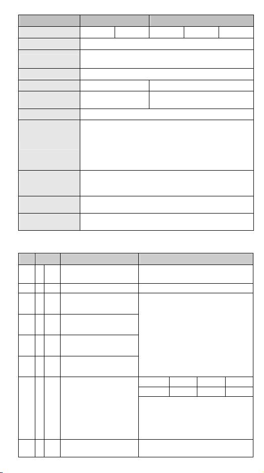
Analog / Digital module Voltage input Current input
Hardware Resolution
16 bits 16 bits 16 bits 15 bits 15 bits
Input impedance < 0.5Ω
Overall accuracy
±0.3% when in full scale (25°C, 77°F)
±0.5% when in full scale within the range of 0 ~ 55°C (32 ~ 131°F)
Response time 250μs / each channel
Max. output current 1KΩ ~ 2MΩ -
Tolerance carried
impedance
- 0Ω~500Ω
Digital data format 2’s complement of 16 bits, 15 significant bits
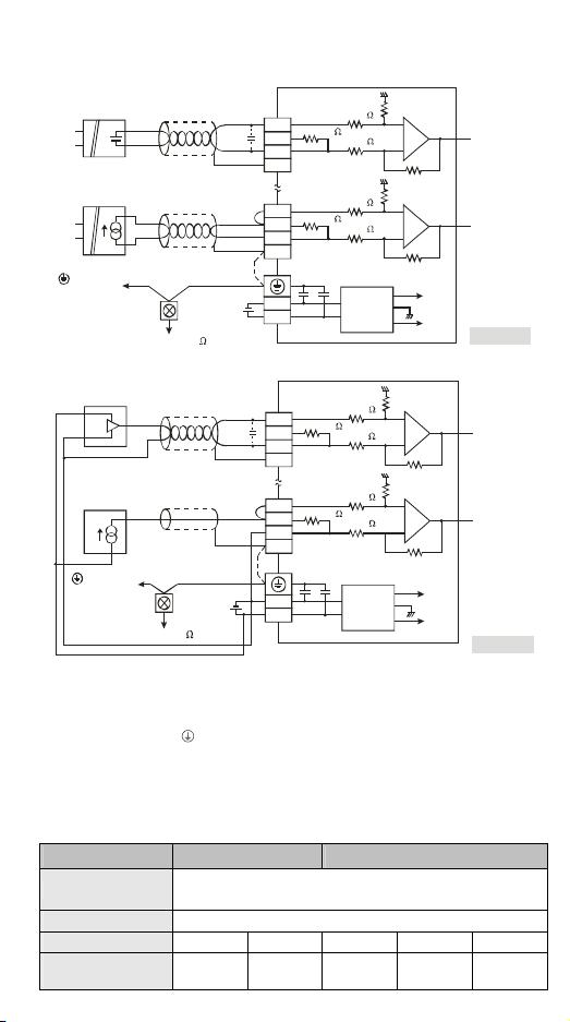
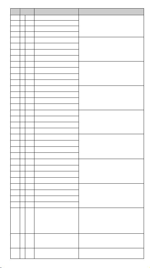
Isolation method
Optical coupler isolation between digital circuits and analog circuits.
No isolation among analog channels.
500VDC between digital circuits and Ground
500VDC between analog circuits and Ground
500VDC between analog circuits and digital circuits
500VDC between 24VDC and Ground
Series connection to
DVP-PLC MPU
Connectable to the left side of MPU, numbered from 100 to 107
according to the position of module from the closest to farthest to
MPU.
Operation/storage
temperature
Operation: 0°C~55°C (temp.), 50~95% (humidity), Pollution degree2
Storage: -25°C~70°C (temp.), 5~95% (humidity)
Vibration/shock
immunity
International standards: IEC61131-2, IEC 68-2-6 (TEST Fc)/
IEC61131-2 & IEC 68-2-27 (TEST Ea)
Control Register
CR# Attrib. Register name Explanation
#0 O R
Model name
Set up by the system:
DVP04AD-SL model code = H’4400
#1 O R
Firmware version
Display the current firmware version in hex.
#2 X R/W
CH1 input mode setting
#3 X R/W
CH2 input mode setting
#4 X R/W
CH3 input mode setting
#5 X R/W
CH4 input mode setting
Input mode: Default = H’0000.
Take CH1 for example:
Mode 0 (H’0000): Voltage input (±10V)
Mode 1 (H’0001): Current input (±20mA)
Mode 2 (H’0002): Current input (0~+20mA)
Mode 3 (H’0003): Current input (+4~+20mA)
Mode 4 (H’0004): Voltage input (±5V)
Mode 5 (H’0005): Voltage input (0V~+5V)
Mode 6 (H’0006): Voltage input (1V~+5V)
Mode -1 (H’FFFF): Channel 1 unavailable
b15 ~ b12 b11 ~ b8 b7 ~ b4 b3 ~ b0
CH4 CH3 CH2 CH1
#6 X R/W
History mode
Only average values are recorded.
Default = H’0000. Take CH1 for example:
K0: Disable (Default). K1: Single. K2: Auto.
K3: Rising Edge Triggered
K4: Falling Edge Triggered
#7 X R/W
History command
Refer to table of history command for detail.
Default = H’0000

 我的内容管理
收起
我的内容管理
收起
 我的收益 登录查看自己的收益
 我的积分
登录查看自己的积分
我的积分
登录查看自己的积分
 我的C币
登录后查看C币余额
我的C币
登录后查看C币余额
 我的收藏
我的收藏  我的下载
我的下载  下载帮助
下载帮助 


评论0