没有合适的资源?快使用搜索试试~ 我知道了~
首页MIT辐射实验室丛书 V1-RADAR SYSTEM ENGINEERING
资源详情
资源评论
资源推荐

CHAPTER 1
INTRODUCTION
BY LOUIS N. RIDENOUR
101. What Radar Does. —Radar is an addition to man’s sensory
equipment which affords genuinely new facilities.
It enables a certain
class of objects to be “seen”
—that is, detected andlocated—at distances
far beyond those at which they could be distinguished by the unaided
eye. This ‘(seeing” is unimpaired by night, fog, cloud, smoke, and most
other obstacles to ordinary vision.
Radar further permits the measure-
ment of the range of the objects it “sees” (this verb will hereafter be used
without apologetic quotation marks) with a convenience and precision
entirely unknown in the past.
It can also measure the instantaneous
speed of such an object toward or away from the observing station in a
simple and natural way.
The superiority of radar to ordinary vision lies, then, in the greater
distances at which seeing is possible with radar, in the ability of radar to
work regardless of light condition and of obscuration of the object being
seen, and in the unparalled ease with which target range and its rate of
change can be measured. In certain other respects radar is definitely
inferior to the eye. The detailed definition of the picture it offers is very
much poorer than that afforded by the eye.
Even the most advanced
radar equipment can on]y show the gross outlines of a large object, such
as a ship; the eye can—if it can see the ship at all—pick out fine details
such as the rails on the deck and the number or character of the flags at
the masthead. Because of this grossness of radar vision, the objects
that can usefully be seen by radar are not as numerous as the objects
that canabe distinguished by the eye.
Radar is at its best in dealing with
isolated targets located in a relatively featureless background, such as
aircraft in the air, ships on the open sea, islands and coastlines, cities in
a plain, and the like. Though modern high-definition radar does afford
a fairly detailed presentation of such a complex target as a city viewed
from the air (see, for example, Fig. 335), the radar picture of such a
target is incomparably poorer in detail than a vertical photograph taken
under favorable conditions would be.
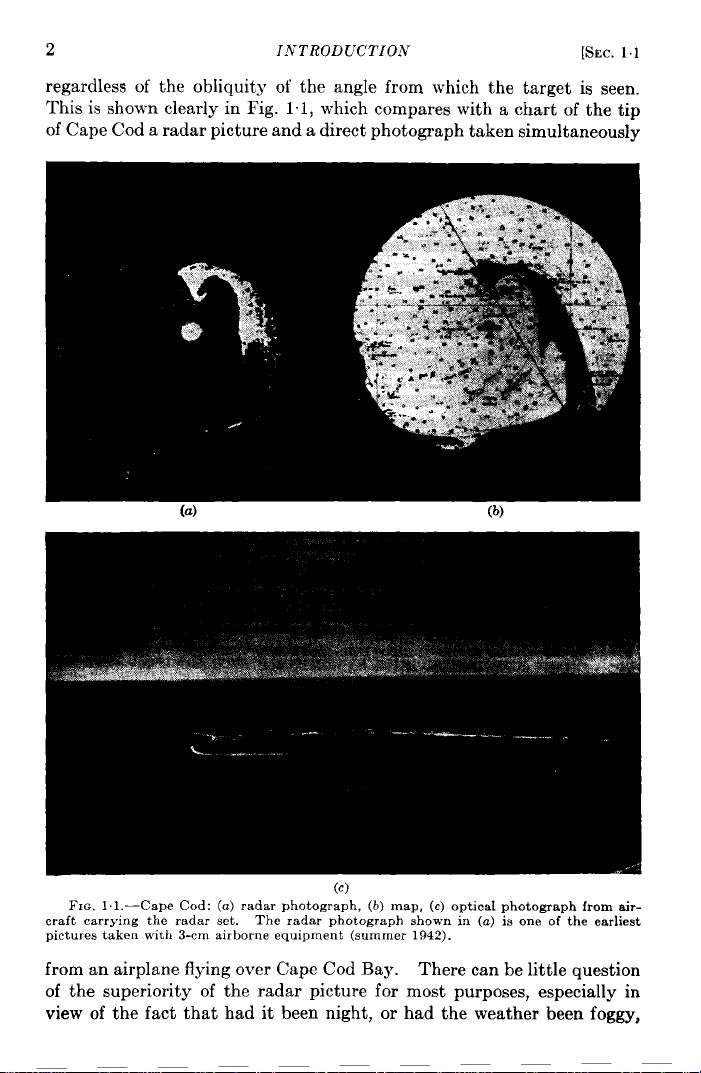
One further property of radar is worth remarking: its freedom from
difficulties of perspective, By suitable design of the equipment, the
picture obtained from a radar set can be presented as a true plan view,
1


SEC.12]
HOW RADAR WORKS 3
the radar picture would have been unaffected while photography or
ordinary vision would have been useless.
1.2. How Radar Works.—The coined word rodaris derived from the
descriptive phrase
“radio detection and ranging. ” Radar works by
sending out radio waves from a transmitter powerful enough so that
measurable amounts of radio energy will be reflected from the objects to
beseenby theradar toaradio receiver usually located, for convenience,
at the same site as the transmitter.
The properties of the received echoes
are used to form a picture or to determine certain properties of the objects
that cause the echoes. Theradar transmitter may send out c-w signals,
or frequency-modulated c-w signals, or signals modulated in other ways.
Many schemes based on transmissions of various sorts have been proposed
and some of them have been used. Chapter 5 of this book treats the
general radar problem, in which any scheme of transmitter modulation
may be used, in a very fundamental and elegant way.
Despite the great number of ways in which a radar system can in
principle be designed, one of these ways has been used to such an over-
whelming degree that the whole of this book, with the exception of Chap.
5, is devoted to it. When radar is mentioned without qualification in
this book, pulse radar will be meant.
NTOapology for this specialization
is needed. Thousands of times as much effort as that expended on all
other forms of radar put together has gone into the remarkably swift
development of pulse radar since its origin in the years just before World
War II.
In pulse radar, the transmitter is modulated in such a way that it
sends out very intense, very brief pulses of radio energy at intervals that
are spaced rather far apart in terms of the duration of each pulse. During
the waiting time of the transmitter between pulses, the receiver is active.
Echoes are received from the nearest objects soon after the transmission
of the pulse, from objects farther away at a slightly later time, and so on.
When sufficient time has elapsed to allow for the reception of echoes from
the most distant objects of interest, the transmitter is keyed again to
send another very short pulse, and the cycle repeats.
Since the radio
waves used in radar are propagated with the speed of light, c, the delay
between the transmission of a pulse and the reception of the echo from
an object at range R will be
(1)
the factor 2 entering because the distance to the target has to be traversed
twice, once out and once back, Figure 1.2 shows schematically the
principle of pulse radar.
The linear relation between delay time and range shown in Eq. (I) is

4
IN TRODUC7”ION
flik~c
‘<2”’”
Target
[SEC.1.2
\
+-4 \
---
----
Radar
Y’&’’@’”a’ 5
Target
.4!... -
_&.- ~
Radar
+)
Yz’o’ti’”e’
Target
JL~~=~
(c) ,%
Radar
_L...__
.,:>( “
@@3
Target
....$~L =+9--
.
—
Radar
FIG.1.2.—Theprincipleof pulseradar.
(a) Pulsehasjust beenemittedfromradar
aat. (b)Pulaereachestarget. (.) Scatteredenergy,eturnsfromtarget;transZnittedpul`e
carrieOon, (d) Echopulsereachesradar.

SEC.1.2]
HOW RADAR WORKS
5
theclue totheease tithwtich range can remeasured by radar. Range
measurement is reduced to a measurement of time, and time can be
measured perhaps more accurately than any other basic physical quan-
tity. Because the velocity of light is high, the intervals of time that
must be measured in radar are short.
Numerically, the range corre-
sponding to a given delay time is 164 yd for each microsecond elapsing
between the transmission of the pulse and the reception of the echo. If
it is desired to measure range to a precision of 5 yd, which is necessary in
some applications of radar, time intervals must be measured with a
precision better than & psec. Modern electronic timing and display
techniques have been developed to such a point that this can readily be
done.
One of the simplest ways in which radar echo signals can be displayed
is shown in Fig. 1.3. The beam of a cathode-ray tube is caused to begin
a sweep from left to right across the face of the tube at the instant a pulse
is sent from the transmitter.
The beam is swept to the right at a uniform
rate by means of a sawtooth waveform applied to the horizontal deflection
plates of the CRT. The output signals of the radar receiver are applied
to the vertical deflection plates.
To ensure that the weakest signals
that are at all detectable are not missed, the over-all gain of the receiver
is high enough so that thermal noise originating in the receiver (Sec. 2.7)
is perceptible on the display. The two signals that rise significantly
above this noise in Fig. 1.3 are, on the left, the “tail” of the transmitted
剩余747页未读,继续阅读


安全验证
文档复制为VIP权益,开通VIP直接复制

评论0