没有合适的资源?快使用搜索试试~ 我知道了~
首页论文研究 - 基于LED的可见光通信实时视频传输
为了实现可见光通信系统的视频图像传输和出色的照明功能,提出了一种基于LED的可见光通信方法和系统。 基于现场可编程门阵列(FPGA)硬件,RS通道编码被应用于可见光通信系统。 提出了一种脉冲位置决策算法,该算法应用于可见光通信系统的接收机中,以满足信号的无差错决策。 系统设计基于模数转换电路,为脉冲位置决策算法提供了较大的信号动态范围,并基于偏置电路设计了LED驱动器,实现了信号的快速宽带调制。 。 测试结果表明,脉冲位置决策算法与Reed-Solomon编解码器的组合应用可以减少系统信号的误差,满足信号的实时,可靠传输。 该系统可以实时显示接收器接收到的视频,整个系统的通讯距离可达5 m。
资源详情
资源评论
资源推荐

Int. J. Communications, Network and System Sciences, 2017, 10, 58-68
http://www.scirp.org/journal/ijcns
ISSN Online: 1913-3723
ISSN Print: 1913-3715
DOI: 10.4236/ijcns.2017.108B007
August 14, 2017
Real-Time Video Transmission of Visible Light
Communication Based on LED
Mingsong Chen, Jie Guo, Xiao Xu, Minglan Liang
School of Information and Communication, Guilin University of Electronic Technology, Guilin, China
Abstract
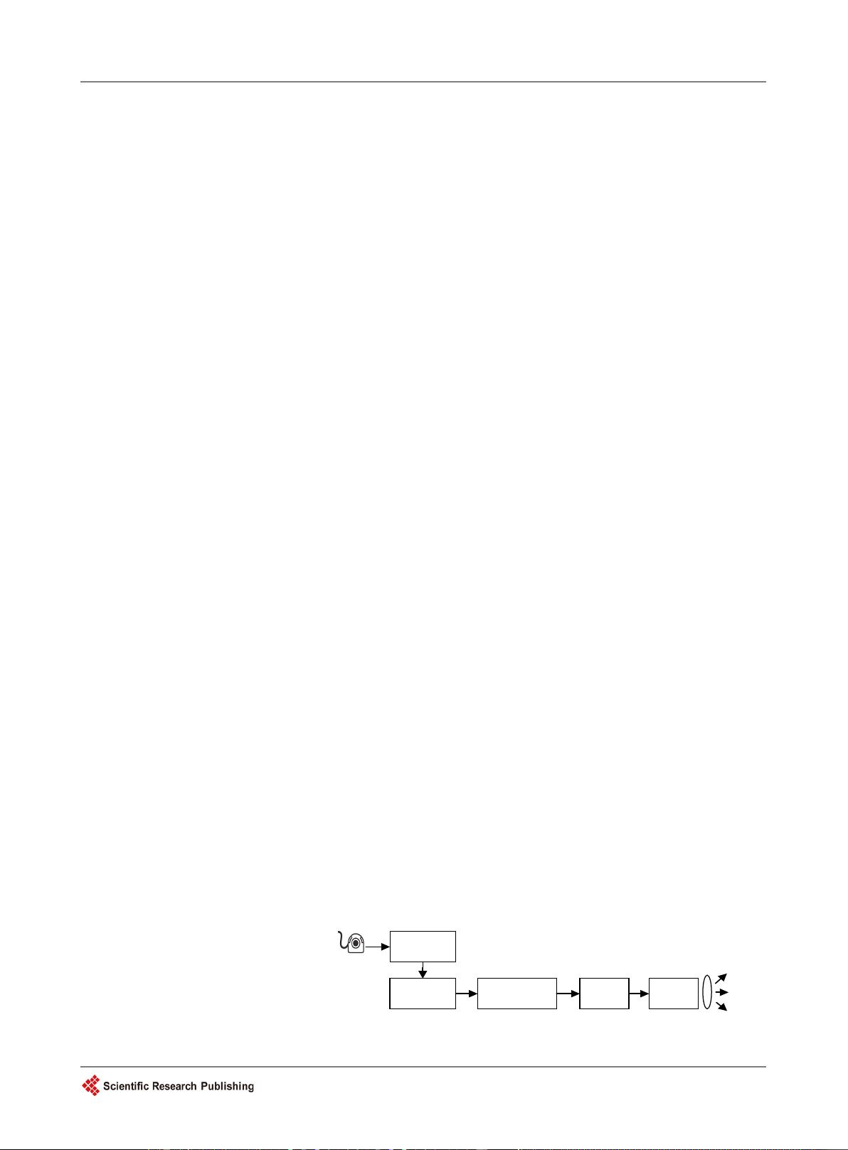
In order to realize the video image transmission and the excellent lighting
function of the visible light communication system, a LED-
based visible light
communication method and system is proposed. Based on the field pr
o-
grammable gate array (FPGA) hardware,
the RS channel coding is applied to
the visible light communication system. A pulse position decision algorithm is
proposed,
which is applied to the receiver of the visible light communication
system to meet the error-free decision of the signa
l. The design of the system
is based on the analog-to-digital conversion circuit,
which provides a large
signal dynamic range for the pulse position decision algorithm,
and designs
the LED driver based on the bias circuit to realize the fast broadband modul
a-
tion of the signal. The test results show that the combined application of pulse
position decision algorithm and Reed-Solomon
codec can reduce the error of
system signal and meet the real-
time and reliable transmission of signal. The
system can display the received video in real time from the receiver,
and the
whole system communication distance up to 5 m.
Keywords
Visible Light Communication, LED, Reed-Solomon, Pulse Position Decision
,
Video Transmission
1. Introduction
This template, created in MS Word 2007, provides authors with most of the
formatting With the LED equipment and craft work updating, visible light
communication based on LED technology is becoming a key research direction
of wireless optical communication [1]. The previous studies focus on the simula-
tion of modulation and coding, as well as the conceptual experimental demon-
stration, the purposes are to achieve fast and strong anti-interference ability of
VLC system [2] [3]. Based on the previous research, this treatise proposes a
How to cite this paper:
Chen, M.S.,
Guo,
J.,
Xu, X. and Liang, M.L. (2017) Real-
Time
Video Transmission of Visible Light Co
m-
munica
tion Based on LED.
Int. J. Comm
u-
nications
,
Network and System Sciences
,
10
, 58-68.
https://doi.org/10.4236/ijcns.2017.108B007
Received:
April 19, 2017
Accepted:
August 11, 2017
Published:
August 14, 2017

M. S. Chen et al.
59
pulse position decision algorithm and combines the RS coding method to im-
prove the reliability and effectiveness of VLC system, which both based on
FPGA to realize. At the same time, the driver circuit of LED and amplifying cir-
cuit are designed, the real-time video is processed in this paper, finally at the re-
ceiving end can display the monitors information from the transmitting end.
The dual functions of visible light communication system about lighting and
communication both realized in this paper.
2. Transmitter Design
Through the real-time video acquisition, the analog video signal is converted
into digital signal, the signal processing is mainly completed on the FPGA plat-
form, STM32 as the main control device. The camera collects real-time video
information, and converts it into digital component by analog-digital composite
video decoder (TW2867). The decoder integrates anti aliasing filter and COMS
analog to digital converter, as well as the PLL can output 108 MHz clock, pro-
grammable tone, saturation, sharpness and other parameters. The transmitter
achieves the function of video acquisition and conversion. Principle diagram of
the transmitting terminal is as shown in
Figure 1.
2.1. Signal Processing of Transmitter
RS encoding method has excellent characteristics, strong correction ability and
higher efficiency in the linear block code, the group code length is short with
good performance [4]. RS (15, 9) encoding can be used to deal with burst errors
in visible light communication. Based on the finite field GF (24), the block
length n is 15 (2
4
− 1), the message length k is 9, the parity length e is n-k there-
fore is 6, the maximum error correction capability t is 3, the minimum code dis-
tance d is 7.
The generate polynomial expression is:
( )
6543 2
7 9 3 12 10 12xx x x x x x
=++++ ++g
(1)
The native original polynomial expression is:
(
)
4
1xxx= ++p
(2)
Therefore, the resulting matrix is:
1
2
1 0 ... 0 0 (mod ( ))
0 1 ... 0 0 (mod ( ))
[]
...
0 0 ... 0 1 (mod ( ))
n
n
k
nk
x gx
x gx
G Ip
x gx
−
−
−
= =
(3)
Coding
processing
Signal
amplification
LED
source
BIAS
driver
Camera
Video
processing
Figure 1. Principle diagram of the transmitting terminal.

M. S. Chen et al.
60
According to the above formula, the formula after encoding is:
() ()mod () ()
rr
Cx xux gx xux= +
(4)
where
x
is the original element, and
t
is the error tolerance,
x
r
u
(
x
)mod
g
(
x
)
represents the remainder of
x
r
u
(
x
) divided by
g
(
x
).
The native original polynomial expression can be calculated by the regenpoly
instructions in Matlab. In the FPGA encoding circuit is designed based on
g
(
x
)
multiplication or division method. The structure is realized by the current shift
register structure, in which the adder is exclusive OR and not-carry, multiplier
into the form of modulo two sums. The algorithm is constructed by the function
[5]. The coding structure is shown in
Figure 2.
2.2. Driving Circuit Design
Designed with Bias-T driver circuit, with ultra-high bandwidth, and can achieve
analog digital dual-signal modulation. Light source drive circuit shown in
Fig-
ure 3, the FB pin of constant current bias chip is the voltage loop feedback pin,
combine with its peripheral circuit for constant voltage regulation, protecting
LED and so on [6] [7]. ISP pin is the current feedback resistor of the positive
connection terminal, can protect short circuit. ISN is the current feedback resis-
tor negative connection terminal, the Bias-T drive circuit make light source
work in the linear work area, the electrical signal superimposed on the DC bias.
According to the AC frequency of capacitor and inductance, fC = 1/(2πRC)
R1 R2
R2t-1
strobe
register
Output
inout
g0
g1 g2 g2t-1
Figure 2. RS coding assumption diagram.
Vc
R6
R1
C2
R2
R3
C1
RF
out
Vdd
GND
Vdd
Bias-T
Amplified signal
ISP
FB
Vin
UVLO
CTRL
R4
R5
L1
ISN
Figure 3. LED driver circuit.
剩余10页未读,继续阅读
安全验证
文档复制为VIP权益,开通VIP直接复制

评论0