
Getting Started with I
2
C in PSoC
®
1
www.cypress.com Document No. 001-50987 Rev. *C 5
I
2
C in PSoC 1
In PSoC 1, I
2
C is handled by a dedicated I
2
C hardware
(HW) block. This HW block removes much of the I
2
C
processing burden from the CPU, freeing the CPU to do
important real-time tasks.
Table 1. I
2
C HW Block Differences
Device
Master
Slave
HW Addr
Match
Two I
2
C
Blocks
20x34
No
Yes
No
No
20xx6A
No
Yes
Yes
No
21x23
Yes
Yes
No
No
21x34
Yes
Yes
No
No
22xxx/21x45
Yes
Yes
No
No
23x33
Yes
Yes
No
No
24x23A
Yes
Yes
No
No
24x94
Yes
Yes
No
No
27x43
Yes
Yes
No
No
28xxx
Yes
Yes
Yes
Yes
29x66
Yes
Yes
No
No
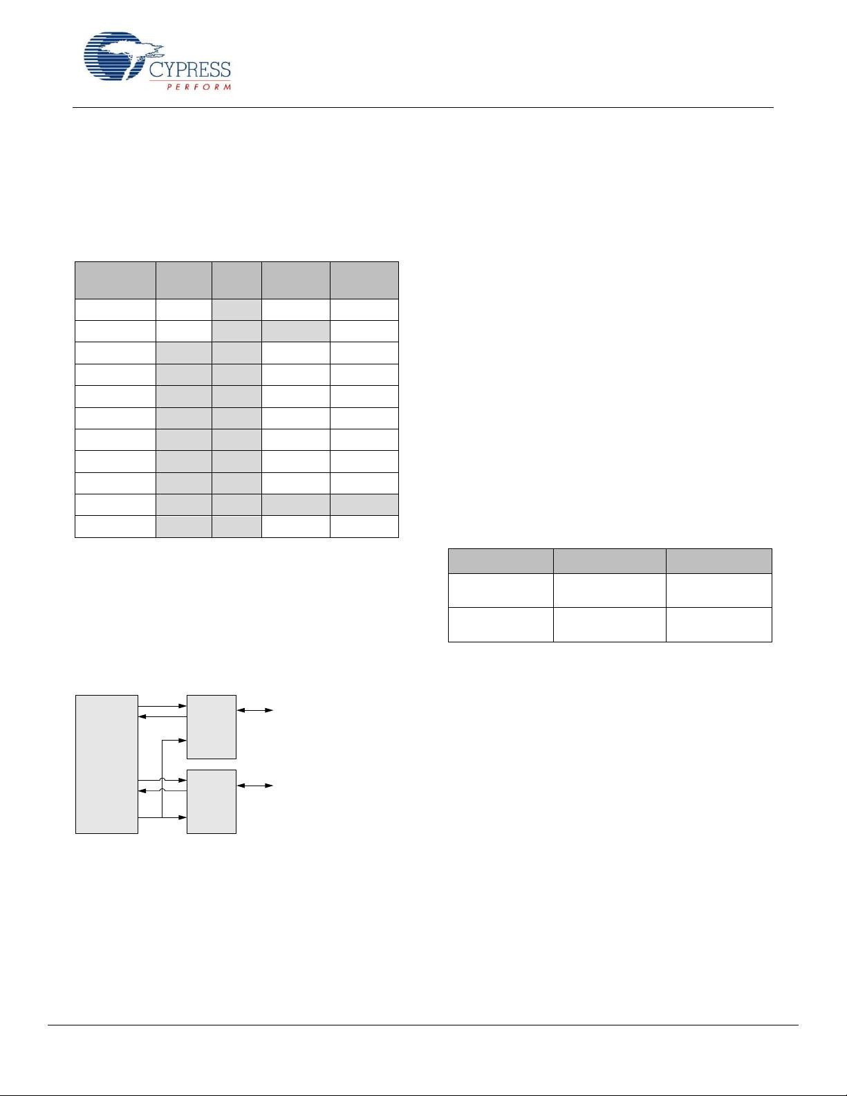
Hardware
The basic structure of this block is similar throughout most
PSoC 1 devices; see Table 1 for the differences between
the part families. As seen in Figure 10, the hardware block
allows P1.5, P1.7 or P1.1, P1.0 to connect to the I
2
C bus.
Cypress recommends avoiding P1.1, P1.0 for I
2
C; these
lines are used for programming.
Figure 10. I
2
C Hardware Block
GPIO
GPIO
SDA_OUT
SDA_IN
SCL_OUT
SCL_IN
I2CEN
SDO
SDI
SDO
SDI
SDE
SDE
I
2
CBLK
SDA
SCL
I
2
C Bus
Port1[5]
or
Port1[0]
Port1[7]
or
Port1[1]
The hardware block is a simple block that handles all the
status and timing requirements of the I
2
C transaction. This
block generates the I
2
C clock when it is in master mode. It
also shifts I
2
C data in and out of the PSoC 1. The block
reports status of I
2
C transactions and errors.
The block is only capable of receiving or transmitting one
byte of data at a time. At each byte boundary, the block
will generate an interrupt. The CPU must service the
interrupt and provide more data to the block, or read the
data the block received. The CPU does not have to
service the block right away as the block holds the SCL
line low until the CPU releases it; this process is referred
to as clock stretching. For more information, see the Clock
Stretching and Interrupt Latency section.
The block is only capable of queuing one transaction at a
time. Multiple starts cannot be queued in the block.
Therefore, user code must ensure that the current I
2
C
transaction is completed before another one is initiated.
The block automatically handles detecting and reporting
arbitration conditions in multi-master environments. In the
case of an arbitration event, the block will report to the
CPU that it lost arbitration. User code should check to see
if arbitration was lost. If arbitration was lost, the code
should retry the transfer.
The I
2
C HW block will generate an interrupt on three
conditions: Tx and Rx byte complete, stop, and bus error.
Bus errors occur when there is a misplaced start or stop
on the bus. When this occurs, all devices on the bus must
stop their current transfer and return to an idle state.
If enabled, the stop interrupt occurs every time there is a
stop condition on the bus.
The byte complete interrupt is triggered at different points
depending on the direction of data flow; see Table 2. This
table applies for both address and data transfers.
Table 2. Byte Complete Interrupt
Mode
Master
Slave
Transmitter
After 8 bits of data
+ ACK/NAK
After 8 bits of data
Receiver
After 8 bits of data
After 8 bits of data
+ ACK/NAK
If more information is required on the functionality of the
I
2
C hardware block, see Appendix A and the I
2
C sections
of the PSoC Technical Reference Manual
Two I
2
C Hardware Blocks in CY8C28xxx
This part family offers two separate I
2
C hardware blocks.
This allows hardware connections to more than one I
2
C
bus at a time. In addition, this block provides hardware
address matching. The hardware only interrupts the CPU
on an address match. However, it does not wake the
PSoC 1 out of a sleep state. After the address, the
hardware will interrupt the CPU according to the
conditions in Table 2.
This block allows for additional I
2
C pin connections on
either P1.2 and P1.6 or P3.0 and P3.2.
Having two I
2
C blocks allows many powerful applications.
Table 3 lists some of the unique applications that can be
achieved with the two I
2
C HW blocks.
剩余24页未读,继续阅读


