
realizing the basic electron emission process from low dimension
materials such as graphene and carbon nanotube. Using a control-
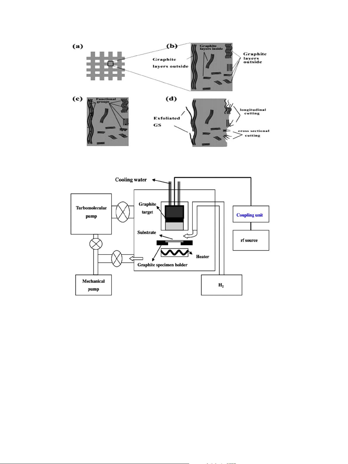
lable capacitive coupled radio frequency (rf) sputtering deposition
system [98], without any catalyst, the vertically aligned ultrathin
graphene nanosheets can be synthesized as shown in Fig. 2. For
the vertical graphene sheets growth process, hydrogen was used
for glow discharge as well as for sputtering carbon coming from
a high-purity graphite target. Utilizing the mixture gas of methane
and hydrogen as precursor, the vertically aligned few-layer gra-
phene was synthesized in the absence of any metallic catalyst by
MPECVD [70]. The unique geometry of the PECVD synthesis
vertical orientation graphene can provide us investigation for the
field emission performance directly. After that the vertically
aligned few-layer graphene were constructed by many researchers
[74–76].
2.4. Printing
A sophisticated method which is widely used in large-scale
applications on different substrate is screen printing technology.
Due to its low manufacture cost, larger scale production, preferable
fabrication condition, the screen-printing method would be suit-
able for electronics technology [77–81]. This pioneer works for
preparing graphene field emitters were reported [82]. The gra-
phene power with organic binders was mixed and then the power
was screen-printed on electrical substrates as an emitter cathode.
At last, these samples were annealed to burn out the organic bin-
ders. For the printed samples, some graphene were wrapped with
each other and some were vertical to the surface of the substrate.
The protruding graphene sheets with sharp edges or tips could be
acted as vertical field emission sites. The unique structure of
printed graphene is beneficial to excellent emission properties.
The method of fabricating vertical graphene field emission cath-
odes based on a conventional screen-printing technique and then
following selective photoetching techniques was also developed
[83]. Fig. 3 presents the schematic for the vertical graphene cath-
odes fabrication process. Mixing graphene solution with negative
ultraviolet (UV) photoresist ink, the photoresist: graphene paste
was prepared and then the paste was screen-printed on the
cleaned indium tin oxide-coated (ITO) glass substrate as shown
Fig. 2. Schematic illustration of the capacitively coupled radio frequency (rf) sputtering system used for the GNS growth. Reproduced with permission from Ref. [98].
Copyright 2013, Elsevier Ltd.
Fig. 1. Schematic of the graphene exfoliation on carbon cloth. (a) Carbon Cloth was woven by carbon fiber. (b) Amplifying diagram for carbon fibers consisted of anisotropic
graphite layers and amorphous carbon. (c) After chemical oxidation, the outside graphite layers were terminated by functional groups. (d) The graphene were exfoliated from
outside graphite layers after heating. Reproduced with permission from Ref. [62]. Copyright 2011, American Institute of Physics.
46 L. Chen et al. / Materials Science and Engineering B 220 (2017) 44–58
剩余14页未读,继续阅读

weixin_38735119
- 粉丝: 7
- 资源: 876
 我的内容管理
展开
我的内容管理
展开


最新资源
- 十种常见电感线圈电感量计算公式详解
- 军用车辆:CAN总线的集成与优势
- CAN总线在汽车智能换档系统中的作用与实现
- CAN总线数据超载问题及解决策略
- 汽车车身系统CAN总线设计与应用
- SAP企业需求深度剖析:财务会计与供应链的关键流程与改进策略
- CAN总线在发动机电控系统中的通信设计实践
- Spring与iBATIS整合:快速开发与比较分析
- CAN总线驱动的整车管理系统硬件设计详解
- CAN总线通讯智能节点设计与实现
- DSP实现电动汽车CAN总线通讯技术
- CAN协议网关设计:自动位速率检测与互连
- Xcode免证书调试iPad程序开发指南
- 分布式数据库查询优化算法探讨
- Win7安装VC++6.0完全指南:解决兼容性与Office冲突
- MFC实现学生信息管理系统:登录与数据库操作
资源上传下载、课程学习等过程中有任何疑问或建议,欢迎提出宝贵意见哦~我们会及时处理!
点击此处反馈


