
www.ams.com/Power-Management/AS1390 Revision 1.7 4 - 20
AS1390A, AS1390B
Datasheet - Pin Assignments
18
LX A I/O
Inductor Connector. Connect an inductor from LX to the output of the buck
converter
2 9 FB_BUCK A I/O
Feedback Buck Pin. Connect this pin to the output of the buck converter
20 7
VDDHP P
Supply for DCDC Buck-Converter
16 3
PGND P
Power Ground
11 14
AGND P
Analog Ground
12 15
EN_BOOST D IN
Enable. Enables the Boost-Controller.
1 = Normal operation;
0 = Shutdown;
13 - MODE_3D D IN
Selection for 3D Mode. (only for AS1390A)
1 = 3D;
0 = 2D;
- Exposed Pad n.c.
Exposed Pad. This pad is not connected internally. Can be left floating or connect to
GND to achieve an optimal thermal performance.
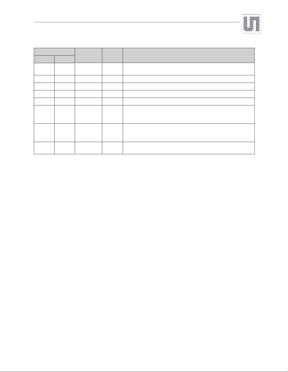
Table 1. Pin Descriptions
Pin Number
Pin Name Pin Type Description
AS1390A AS1390B
剩余19页未读,继续阅读


