

Datasheet 12 Rev. 1.00
2017-07-11
TLD5501-2QV
Dual SYNC Buck Controller with SPI Interface
Power Supply
5 Power Supply
The TLD5501-2QV is supplied by the following pins:
• VIN (main supply voltage)
• VDD (digital supply voltage)
• IVCC_EXT (supply for internal gate driver stages)
The VIN supply, in combination with the VDD supply, provides internal supply voltages for the analog and
digital blocks. In situations where VIN
voltage drops below VDD voltage, an increased current consumption
may be observed at the VDD pin.
The SPI and IO interfaces are supplied by the VDD pin.
IVCC_EXT is the supply for the low side driver stages. This supply is used also to charge, through external
Schottky diodes, the bootstrap capacitors which provide supply voltages to the high side driver stages. If no
external voltage is available this pin must be shorted to IVCC, which is the output of an internal 5 V LDO.
The supply pins VIN, VDD and IVCC_EXT have undervoltage detections.
Undervoltage on VDD supply voltage prevents the activation of the gate driver stages and any SPI
communication (the SPI registers are reset). Undervoltage on IVCC_EXT or IVCC voltages forces a deactivation
of the driver stages, thus stopping the switching activity, but has no effect on the SPI register settings.
Moreover the double function pin EN/INUVLO can be used as an input undervoltage protection by placing a
resistor divider from VIN to GND .
If EN/INUVLO undervoltage is detected, it will turn-off the IVCC voltage regulator, stop switching, stop
communications and reset all the registers.
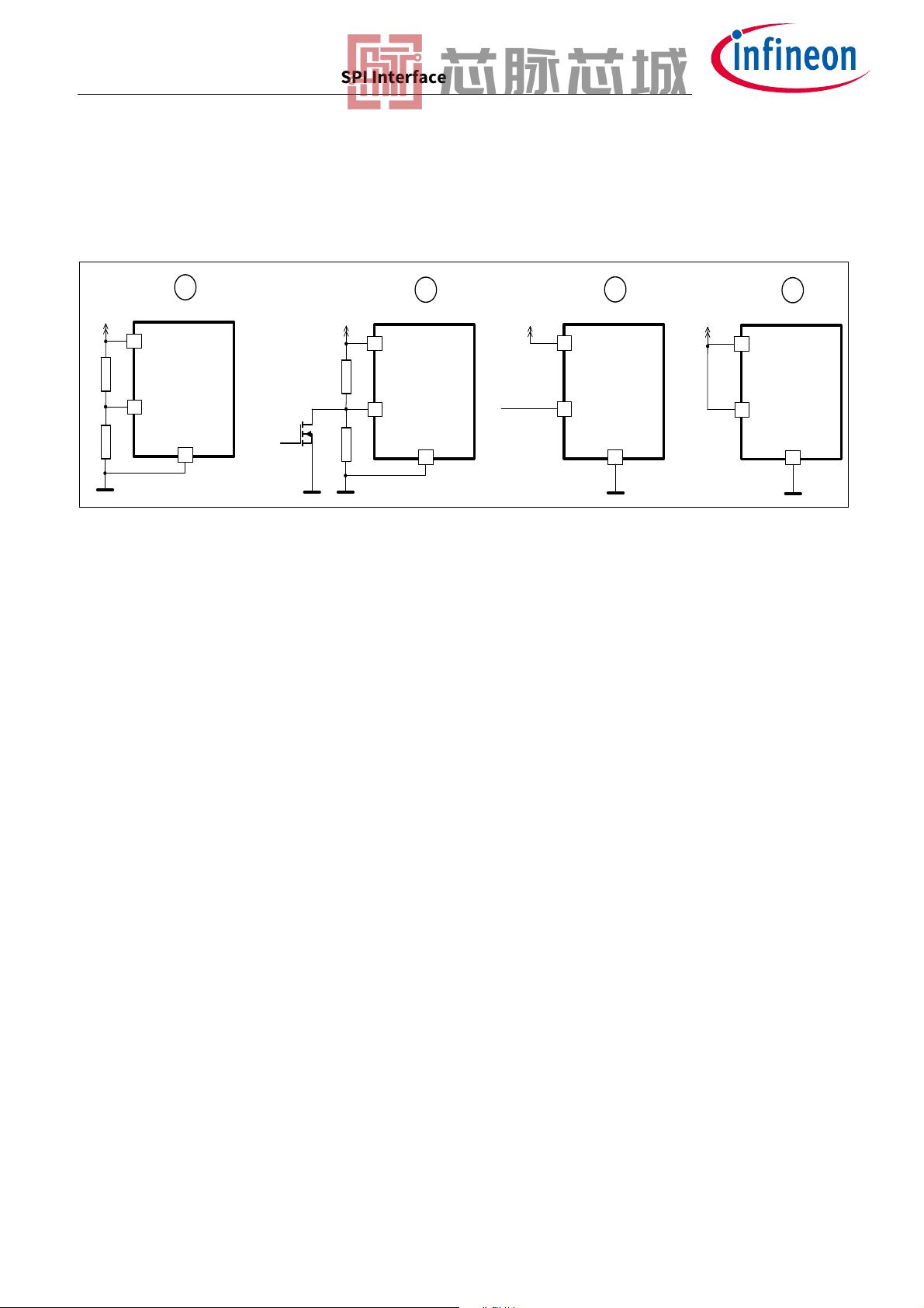
Figure 4 shows a basic concept drawing of the supply domains and interactions among pins VIN, VDD and
IVCC/IVCC_EXT.
Figure 4 Power Supply Concept Drawing
VIN
VREG (5V)
EN/INUVLO
Internal pre-regulated
voltage Supply
VREG
analog
VREG
digital
Bandgap
Reference
LOGIC
Register
Banks
SPI & I/O
VDD
IVCC
LS - Drivers
HS - Drivers
BSTx
SWNx
R
1
R
2
IVCC_EXT
PGND
Undervoltage
detection
Undervoltage
detection

剩余68页未读,继续阅读


