UVM实战指南:采用通用验证方法
"《实用通用验证方法论(UVM)指南》是一本经过精心校对和重新排版的书籍,作者或编者基于原始影印PDF通过OCR技术转录并纠正了错误。这本书去掉了前言和附录,专注于主要内容,特别是关于UVM的详细解释。书中包含了大量的Visio绘制的图表,清晰度更高,旨在帮助读者更好地理解和应用UVM。本书特别关注了UVM在系统验证中的应用,涵盖了UVM的基本概念、测试平台、环境构建、接口通用验证组件(UVCs)以及对象导向编程的基础知识。"
在深入探讨UVM之前,首先需要理解通用验证方法论(UVM)是什么。UVM是一种基于SystemVerilog语言的业界标准验证方法,它为验证数字设计提供了一种可复用和可扩展的框架。UVM的核心在于其面向对象的设计,这使得它可以适应多语言和多种验证策略。
1. 验证规划与覆盖率驱动验证:在UVM中,验证工作是围绕计划和覆盖率指标进行的。这意味着在验证过程中,设计的每个功能和行为都需要有明确的覆盖目标,以确保全面验证。
2. 多语言和方法学:UVM允许在不同的验证环境中集成多种语言和验证技术,增强了灵活性和兼容性。
本书的特色在于它不仅解释了UVM的基本概念,还提供了如何使用这本书的指导,包括如何运行示例和书中的约定。
3. UVM概述:
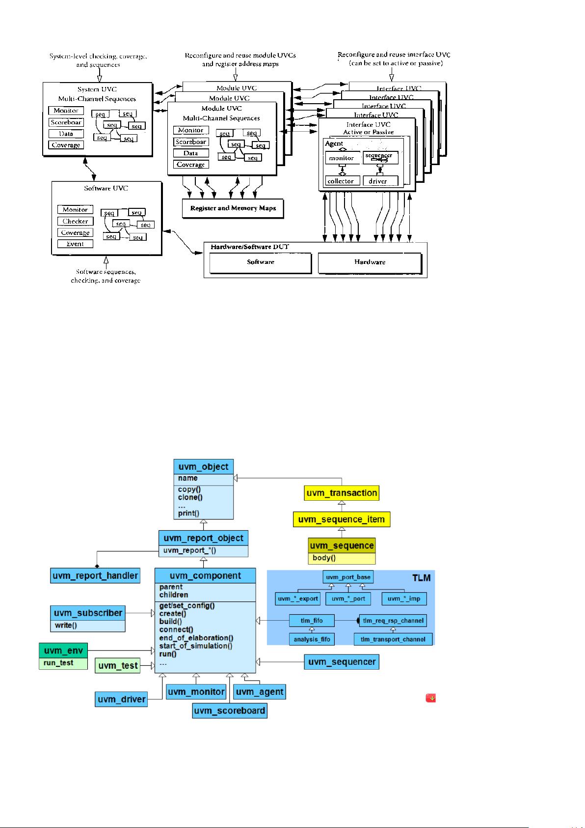
- UVM测试平台和环境:UVM环境是验证设计的核心,它包含了用于模拟设计行为的组件,如代理、序列器、驱动、监视器和收集器。
- 接口UVCs:这些组件处理数据交换,如BFM(总线功能模型)负责与硬件接口交互。
- 测试平台和环境:UVM测试平台包括了所有必要的组件来驱动、监控和评估设计行为。
- 系统和模块UVCs:这些组件用于特定设计层次的验证,例如软件UVCs用于验证软件层面的行为。
- SystemVerilog UVM类库:提供了诸如工厂机制、事务级别建模(TLM)等工具,支持高效、灵活的验证代码编写。
4. 对象导向编程(OOP)基础:作为UVM的基础,OOP是设计和实现UVM组件的关键。书中介绍了OOP的基本概念,包括类、对象和程序的定义,以及在分布式开发环境中的应用。此外,还讨论了关注点分离的原则,这是创建可维护和可扩展的验证代码的关键。
《实用通用验证方法论(UVM)指南》是学习和实践UVM的宝贵资源,通过它,读者可以深入了解UVM如何提升系统级验证的效率和质量。无论是对于新手还是经验丰富的验证工程师,都能从中受益。

UVCs to drive traffic for some time while polling the DUT status through the DUT
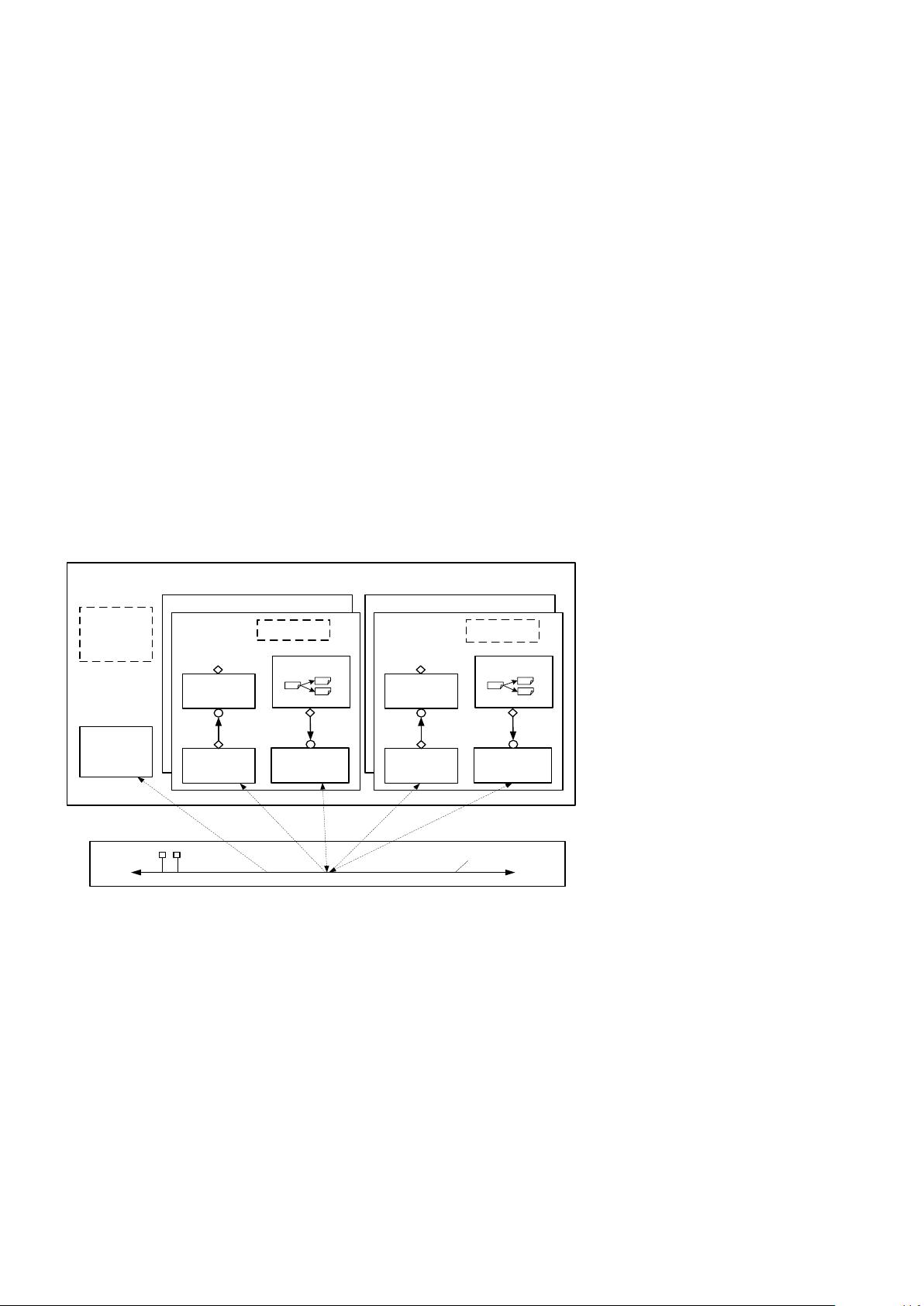
The repository block on the right illustrates a company UVC repository that can contain internally implemented or
commercial UVCs which can be leveraged by all verification projects.
2.2 Interface UVCs
The interface UVCs standard structure includes the following elements:
2.2.1 Data Items
Data items represent stimulus transactions that are input to the DUT, Examples include networking packets, bus
transactions, and instructions. The fields and attributes of a data item are derived from the data items specification. For
example, the Ethernet protocol specification defines valid values and attributes for an Ethernet data packet. In a typical
test, many data items are generated and sent to the DUT. By intelligently randomizing data item fields using SystemVerilog
constraints, you can create a large number of meaningful tests and maximize coverage.
2.2.2 Driver/Bus Functional Model (BFM)
A driver is an active entity which emulates logic that drives the DUT. A typical driver repeatedly pulls data items
generated by a sequencer (advanced generator) and drives it to the DUT by sampling and driving the DUT signals. For
example, a driver controls the read/write signal, address bus, and data bus for a number of clock cycles to perform a write
transfer. (If you have created a verification environment in the past, you probably have implemented driver functionality.)
2.2.3 Sequencer
A sequencer is an advanced stimulus generator that controls the items provided to the driver for execution. By default,
a sequencer behaves similarly to a simple stimulus generator and returns a random data item upon request from the driver.
This default behavior allows you to add constraints to the data item class in order to control the distribution of randomized
values. Unlike generators that randomize arrays of transactions or one transaction at a time, a sequencer includes many
important built-in features. A partial list of the sequencer’s built-in capabilities includes:
Ability to react to the current state of the DUT for every data item generated
Capture of the order between data items in user-defined sequences, which forms a more structured and meaningful
stimulus pattern
Enabling time modeling in reusable scenarios
Support for declarative and procedural constraints for the same scenario
System-level synchronization and control of multiple interfaces
2.2.4 Monitor
A monitor is a passive entity that samples DUT signals but does not drive them. Monitors collect coverage information
and perform checking. Even though reusable drivers and sequencers drive bus traffic, they are not used for coverage and
checking—monitors are used instead. A monitor performs the following functions:
Collects transactions (data items). A monitor extracts signal information from a bus and translates the information
into a transaction that can be made available to other components and to the test writer. Note that this activity might
be performed by a collector component that is described below.


剩余198页未读,继续阅读
点击了解资源详情
292 浏览量
点击了解资源详情
2022-06-04 上传
2021-02-26 上传
133 浏览量
2009-03-02 上传
137 浏览量
686 浏览量

oscillator
- 粉丝: 1
 我的内容管理
展开
我的内容管理
展开


最新资源
- Linux中断处理源码深度解析与分类探讨
- Linux内核启动揭秘:源代码入门指南
- SQL Server COM扩展:在存储过程中操作COM对象
- 2008年软件设计师考试大纲:计算机与软件工程知识
- Windows NT 2000系统信息与控制
- TD-SCDMA技术详解:从基础到物理层
- 华为SCOUNIX培训教材:UNIX命令详解
- C#入门指南:从基础到面向对象编程
- 医院信息系统设计:数据库架构与需求分析
- CSS布局与Web标准实战:3天掌握核心技术
- ORACLE系统详解:分布式处理与协同开发环境
- Lucene:Java全文检索引擎工具包详解
- SAP清帐操作与培训揭秘
- 深入学习Java SWT图形用户界面编程
- Java反射机制详解与应用
- C#编程基础与实战指南
