

3GPP TS 25.101 V6.19.0 (2009-03)16Release 6T
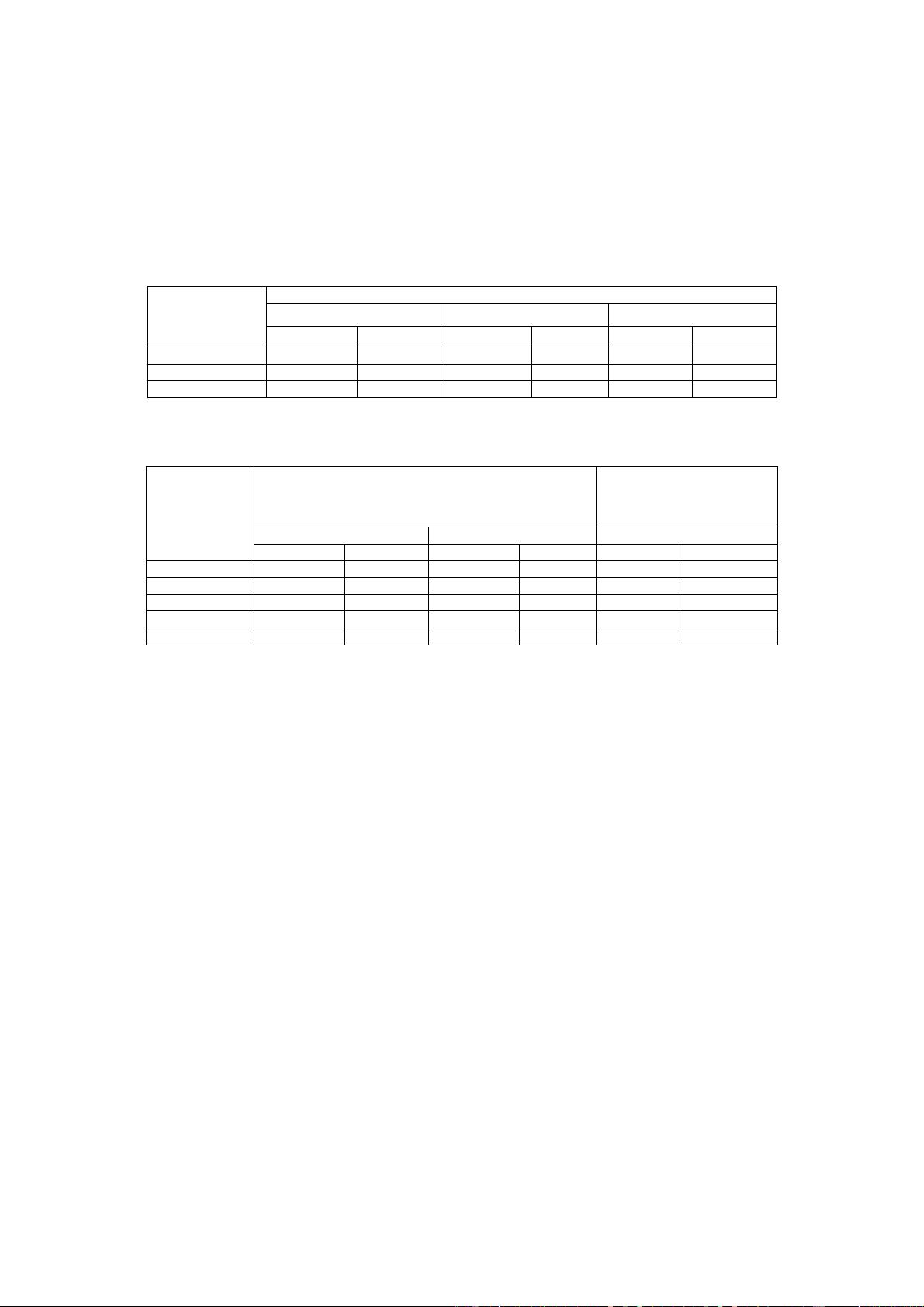
Band I
+33 +1/-3 +27 +1/-3 +24 +1/-3 23 +2/-2 +21 +2/-2
Band II
- - - - +24 +1/-3 23 +2/-2 +21 +2/-2
Band III
- - - - +24 +1/-3 23 +2/-2 +21 +2/-2
Band IV
- - - - +24 +1/-3 23 +2/-2 +21 +2/-2
Band V
- - - - +24 +1/-3 23 +2/-2 +21 +2/-2
Band VI
- - - - +24 +1/-3 23 +2/-2 +21 +2/-2
NOTE: The tolerance allowed for the nominal maximum output power applies even for the multi-code DPDCH
transmission mode.
6.2.2 UE maximum output power with HS-DPCCH and E-DCH
The Maximum Power Reduction (MPR) for the nominal maximum output power defined in 6.2.1 is specified in table
6.1A for the values of β
c,
β
d,
β
hs,
β
ec
and β
ed
defined in [8] fully or partially transmitted during a DPCCH timeslot.
Table 6.1A: UE maximum output power with HS-DPCCH and E-DCH
UE transmit channel configuration CM (dB) MPR (dB)
For all combinations of; DPDCH, DPCCH, HS-
DPCCH, E-DPDCH and E-DPCCH
0 ≤ CM ≤ 3.5
MAX (CM-1, 0)
NOTE 1: CM = 1 for β
c
/β
d
=12/15, β
hs
/β
c
=24/15. For all other combinations of DPDCH,
DPCCH, HS-DPCCH, E-DPDCH and E-DPCCH
the MPR is based on the relative
CM difference.
Where Cubic Metric (CM) is based on the UE transmit channel configuration and is given by
CM =CEIL{ [20 * log10 ((v_norm
3
)
rms
) - 20 * log10 ((v_norm_ref
3
)
rms
)] / k, 0.5 }
Where
- CEIL{ x, 0.5 } means rounding upwards to closest 0.5dB, i.e. CM [0, 0.5, 1.0, 1.5, 2.0, 2.5, 3.0, 3.5]
- k is 1.85 for signals where all channelisations codes meet the following criteria CSF, N where N< SF/2
- k is 1.56 for signals were any channelisations codes meet the following criteria C
SF, N
where N ≥ SF/2
- v_norm
is the normalized voltage waveform of the input signal
- v_norm_ref is the normalized voltage waveform of the reference signal (12.2 kbps AMR Speech) and
- 20 * log10 ((v_norm_ref
3
)
rms
) = 1.52 dB
6.2.3 UE Relative code domain power accuracy
The UE Relative code domain power accuracy is a measure of the ability of the UE to correctly set the level of
individual code powers relative to the total power of all active codes. The measure of accuracy is the difference between
two dB ratios:
UE Relative CDP accuracy = (Measured CDP ratio) - (Nominal CDP ratio)
where
Measured CDP ratio = 10*log((Measured code power) / (Measured total power of all active codes))
Nominal CDP ratio = 10*log((Nominal CDP) / (Sum of all nominal CDPs))
The nominal CDP of a code is relative to the total of all codes and is derived from beta factors. The sum of all nominal
CDPs will equal 1 by definition.
NOTE: The above definition of UE relative CDP accuracy is independent of variations in the actual total power of
the signal and of noise in the signal that falls on inactive codes.
3GPP


剩余133页未读,继续阅读


