
IEEE TRANSACTIONS ON INSTRUMENTATION AND MEASUREMENT, VOL. 62, NO. 6, JUNE 2013 1467
A New NVNA Phase Reference for Polyharmonic
Intermodulation Measurements
Yichi Zhang and Maoliu Lin, Senior Member, IEEE
Abstract—The step-recovery-diode-based impulse generator is
a classical picosecond-level impulse-formation technique, whose
strong harmonic nonlinearity under sinusoidal stimulus is widely
utilized as the phase reference of the nonlinear vector network
analyzer (VNA) (NVNA) and large-signal network analyzer for
wideband measurements. This paper further exploits its inter-
modulation nonlinearity under multitone stimulus and proposes a
new approach, rather than the traditional “harmonic” way, of the
NVNA phase reference for future polyharmonic intermodulation
measurements. Experimental results show that this method can
provide plentiful intermodulation components around each har-
monic available and is stable for NVNA use, with the advantages
of flexible local frequency-resolution setup from tens of megahertz
to less than hundreds of hertz.
Index Terms—Harmonic, impulse generator, intermodulation,
multitone stimulus, nonlinear vector network analyzer (VNA)
(NVNA), phase reference, step recovery diode (SRD).
I. INTRODUCTION
T
HE NONLINEAR vector network analyzer (VNA)
(NVNA) is a new kind of measurement system for wide-
bandwidth signals and components. As the upgrade of VNA,
the NVNA can capture the entire magnitude and phase spectra,
like a large-signal network analyzer (LSNA), by adding an extra
receiver channel that measures a harmonic phase (HPR) [1].
This provides the NVNA with capabilities for performing time-
domain measurements and nonlinear tests and modeling.
One traditional approach to acquire the HPR, also known as
the impulse generator or comb generator, is based on the step
recovery diode (SRD) [2]. However, the frequency r esolutions
of these impulse generators are always wider than 100 MHz
when gigahertz harmonic bandwidth is required, due to the
limits of SRD properties. As a result, the modern NVNA, to
meet the need of intermodulation measurements, turns to a new
impulse-generator design method along with the maturity of
indium phosphide (InP) technology [3].
This paper proposes an approach to obtain fine-resolution
intermodulation spectrum lines within the narrow bands at
Manuscript received June 21, 2012; revised October 30, 2012; accepted
December 4, 2012. Date of publication January 25, 2013; date of current
version May 8, 2013. This work was supported in part by the National Natural
Science Foundation of China under Grant 61771062 and in part by the Doctoral
Fund of the Ministry of Education of China under Grant 20112302110033.
The Associate Editor coordinating the review process for this paper was
Dr. Lucas Di Lillo.
The authors are with the School of Electronics Information Engineering,
Harbin Institute of Technology, Harbin 150001, China (e-mail: yi_chi_zhang@
yahoo.com.cn; mllin@hit.edu.cn).
Color versions of one or more of the figures in this paper are available online
at http://ieeexplore.ieee.org.
Digital Object Identifier 10.1109/TIM.2013.2237997
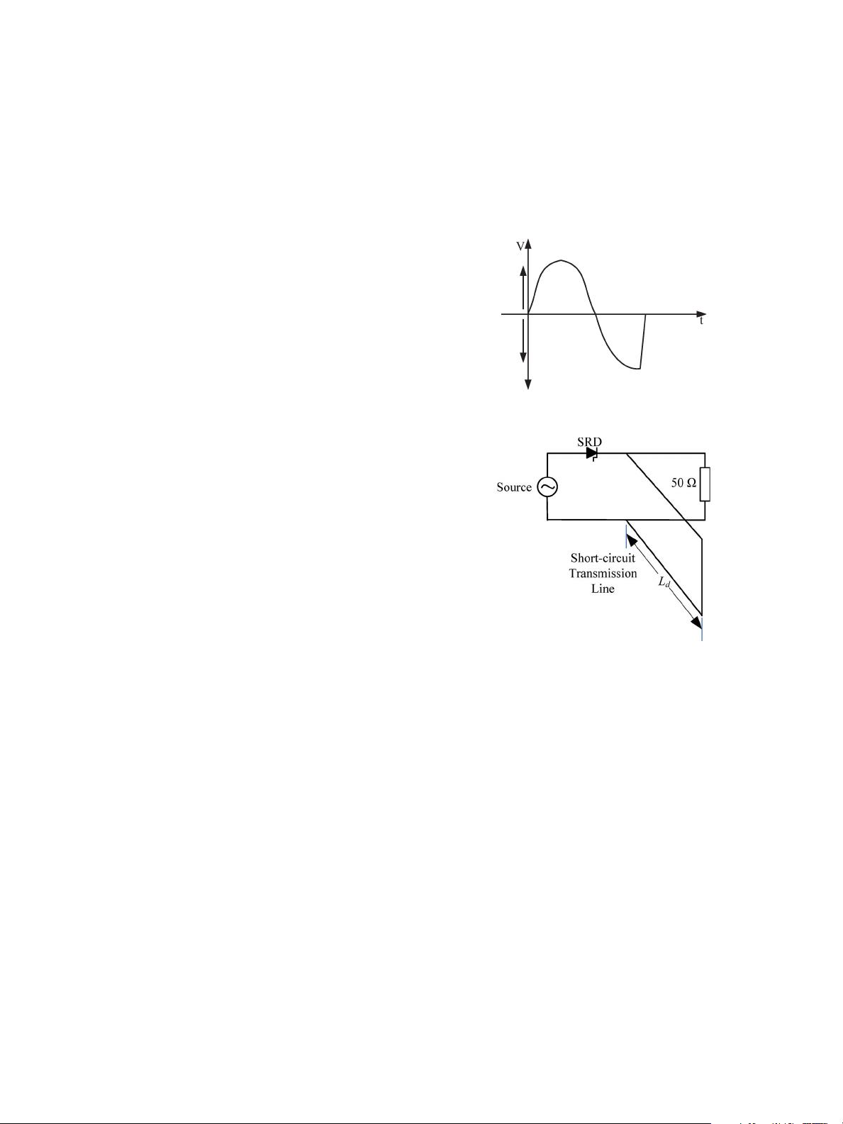
Fig. 1. General response of an SRD under sinusoidal stimulus.
Fig. 2. Circuit diagram of SRD-based impulse generator.
harmonics, based on SRD i mpulse generators under the mul-
titone stimulus rather than traditional sinusoidal ones. This new
application of SRD impulse generators shows the potential to
serve the NVNA as a phase reference for future polyharmonic
intermodulation measurements [4].
II. SRD-B
ASED IMPULSE-FORMATION TECHNIQUE
Fig. 1 shows the general output of an SRD. When stimulated
by a sinusoidal large signal, the SRD abruptly turns off after its
lifetime in the negative half cycle, generating a step function,
the edge of which is further utilized for impulse formation.
Fig. 2 is the circuit diagram of an SRD-based impulse
generator, where a short-circuit transmission line is designed
and used to create a “reflected” and “delayed” copy of the
SRD response at the output port as shown in the upper figure
of Fig. 3. As a result, the original SRD response and its
delayed reflection, traveling along the main and short-circuit
transmission lines, respectively, combine with each other at
the output port and form a desired impulse signal around the
step part as shown in the lower figure of Fig. 3. A detailed
introduction of SRD impulse generators can be found in [5].
0018-9456/$31.00 © 2013 IEEE
下载后可阅读完整内容,剩余5页未读,立即下载

weixin_38653085
- 粉丝: 4
- 资源: 926
 我的内容管理
展开
我的内容管理
展开


最新资源
- 十种常见电感线圈电感量计算公式详解
- 军用车辆:CAN总线的集成与优势
- CAN总线在汽车智能换档系统中的作用与实现
- CAN总线数据超载问题及解决策略
- 汽车车身系统CAN总线设计与应用
- SAP企业需求深度剖析:财务会计与供应链的关键流程与改进策略
- CAN总线在发动机电控系统中的通信设计实践
- Spring与iBATIS整合:快速开发与比较分析
- CAN总线驱动的整车管理系统硬件设计详解
- CAN总线通讯智能节点设计与实现
- DSP实现电动汽车CAN总线通讯技术
- CAN协议网关设计:自动位速率检测与互连
- Xcode免证书调试iPad程序开发指南
- 分布式数据库查询优化算法探讨
- Win7安装VC++6.0完全指南:解决兼容性与Office冲突
- MFC实现学生信息管理系统:登录与数据库操作
资源上传下载、课程学习等过程中有任何疑问或建议,欢迎提出宝贵意见哦~我们会及时处理!
点击此处反馈


