
NCP5623C
www.onsemi.com
3
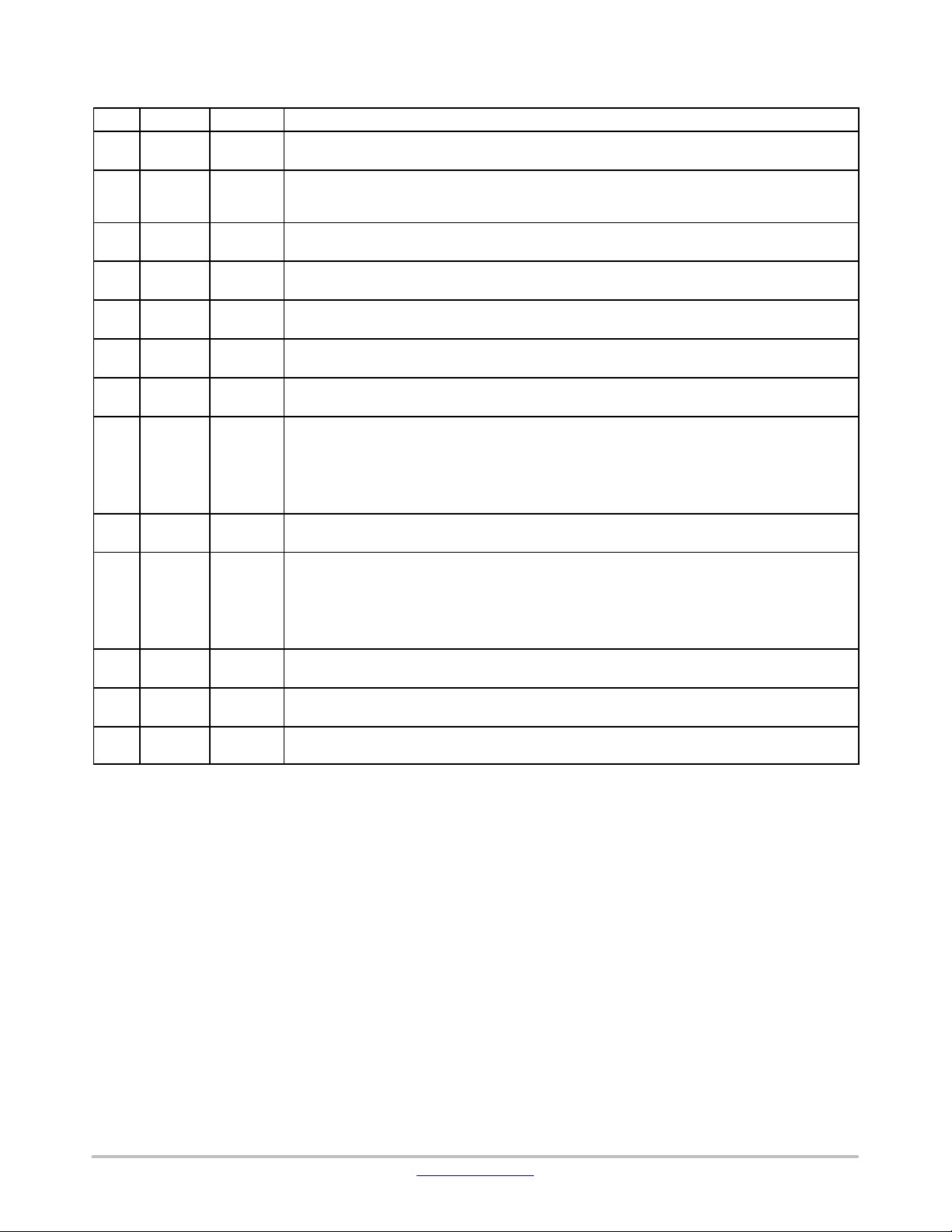
PIN ASSIGNMENT
PIN Name Type Description
1 C1P POWER One side of the external charge pump capacitor (C
FLY
) is connected to this pin, associated with C1N,
pin 12 (Note 1).
2 GND POWER This pin is the GROUND signal for the analog and digital blocks and must be connected to the system
ground. This pin is the GROUND reference for the DC/DC converter and the output current control.
The pin must be connected to the system ground, a ground plane being strongly recommended.
3 LED3 INPUT,
POWER
This pin sinks to ground and monitors the current flowing into the LED3, intended to be used in illu-
mination application (Note 2). The Anode of the associated LED shall be connected to the Vout pin.
4 LED2 INPUT,
POWER
This pin sinks to ground and monitors the current flowing into the LED2, intended to be used in illu-
mination application (Note 2). The Anode of the associated LED shall be connected to the Vout pin.
5 LED1 INPUT,
POWER
This pin sinks to ground and monitors the current flowing into the LED1, intended to be used in illu-
mination application (Note 2).
6 AGND ANALOG
GROUND
This pin copies the Analog Ground and must be connected to the system ground plane.
7 SDA INPUT,
DIGITAL
This pin carries the data provided by the I2C protocol. The content of the SDA byte is used to pro-
gram the mode of operation and to set up the output current (Note 1).
8 I
REF
INPUT,
ANALOG
This pin provides the reference current, based on the internal band−gap voltage reference, to control
the output current flowing in the LED. A 1% tolerance, or better, resistor shall be used to get the high-
est accuracy of the LED biases. An external current mirror can be used to bias this pin to dynamically
set up the I−LED peak current.
In no case shall the voltage at I
REF
pin be forced either higher or lower than the 600 mV provided by
the internal reference.
9 SCL INPUT,
DIGITAL
This pin carries the I2C clock to control the Charge Pump converter and to set up the output current.
The SCL clock is associated with the SDA signal.
10 VOUT OUTPUT,
POWER
This pin provides the output voltage supplied by the Charge Pump converter. The Vout pin must be
bypassed by 1 mF ceramic capacitor located as close as possible to the V
OUT
pin to properly bypass
the output voltage to ground. The circuit shall not operate without such bypass capacitor connected
across the Vout pin and Ground (Note 1).
The output voltage is internally clamped to 5.5 V maximum in the event of a no load situation. On the
other hand, the output current is limited to 40 mA (typical) in the event of a short circuit to ground.
11 VBAT INPUT,
POWER
This pin is the input Battery voltage to supply the analog and digital blocks. The pin must be de-
coupled to ground by a 1 mF or higher ceramic capacitor (Note 1).
12 C1N POWER One side of the external charge pump capacitor (C
FLY
) is connected to this pin, associated with C1P,
pin 1 (Note 1)
− EXPAD GROUND EXPAD is not physically connected to the die. To optimize power dissipation, EXPAD must be connec-
ted to the system (PCB) power ground plane.
1. Using low ESR ceramic capacitor, X5R type, is mandatory to optimize the Charge Pump efficiency and to reduce the EMI.
2. The peak current is 37 mA for each LED, the total charge pump output DC current being limited to 75 mA.
剩余10页未读,继续阅读

li15817260414
- 粉丝: 5
- 资源: 2
 我的内容管理
展开
我的内容管理
展开


最新资源
- 十种常见电感线圈电感量计算公式详解
- 军用车辆:CAN总线的集成与优势
- CAN总线在汽车智能换档系统中的作用与实现
- CAN总线数据超载问题及解决策略
- 汽车车身系统CAN总线设计与应用
- SAP企业需求深度剖析:财务会计与供应链的关键流程与改进策略
- CAN总线在发动机电控系统中的通信设计实践
- Spring与iBATIS整合:快速开发与比较分析
- CAN总线驱动的整车管理系统硬件设计详解
- CAN总线通讯智能节点设计与实现
- DSP实现电动汽车CAN总线通讯技术
- CAN协议网关设计:自动位速率检测与互连
- Xcode免证书调试iPad程序开发指南
- 分布式数据库查询优化算法探讨
- Win7安装VC++6.0完全指南:解决兼容性与Office冲突
- MFC实现学生信息管理系统:登录与数据库操作
资源上传下载、课程学习等过程中有任何疑问或建议,欢迎提出宝贵意见哦~我们会及时处理!
点击此处反馈


