Detailed Explanation of Procedural Statements and Branching Structures in Verilog
发布时间: 2024-09-14 03:15:20 阅读量: 55 订阅数: 38 

Data Structures and Algorithm Analysis in C++ 4th 原版pdf by Weiss
# Introduction to Verilog
Verilog is a Hardware Description Language (HDL) used for modeling, simulating, and synthesizing digital circuits. Within the realm of digital circuit design, Verilog is extensively used in various fields including integrated circuit design, FPGA programming, and digital signal processing.
## Brief Introduction to Verilog
Developed by Gateway Design Automation in 1984, Verilog was later acquired and promoted by Cadence Design Systems. It is an event-driven language that can describe the behavior, structure, and timing characteristics of digital systems.
## Applications of Verilog
Verilog is widely applied in the field of digital circuit design, including but not limited to:
- ASIC Design: Used for the design and verification of custom integrated circuits.
- FPGA Programming: Utilized to configure FPGA chips to perform specific functions.
- Digital Signal Processing: Employed to describe and verify various digital signal processing algorithms and circuits.
## Advantages and Characteristics of Verilog
The advantages and characteristics of Verilog include:
- High abstraction: Allows for the description of complex digital circuit behaviors.
- Easy to learn: Syntax similar to C language, making it easy to grasp and utilize.
- Maintainability: Modular design style facilitates organization and maintenance of code.
In the following chapters, we will delve into the basic concepts, procedural statements, and branch structures in Verilog, as well as how to apply Verilog for digital circuit design.
# Basic Concepts in Verilog
As a hardware description language, Verilog plays a crucial role in digital circuit design. Understanding the basic concepts in Verilog is essential for mastering Verilog programming. This chapter will introduce modules, ports, signals, data types, and concepts related to sequential and combinational logic in Verilog.
### Modules and Ports
In Verilog, a module is an independent functional unit that may contain combinational logic, sequential logic, etc. Modules communicate with other modules or the external environment through ports. Ports are categorized into input ports (input), output ports (output), bidirectional ports (inout), etc.
```verilog
module my_module (
input wire A, // Input port A
input wire B, // Input port B
output reg Y // Output port Y
);
always @(*) begin
Y = A & B; // Implementing AND gate logic
end
endmodule
```
### ***
***mon data types include wire, reg, integer, real, etc. Wire is used for signals with continuous assignments, while reg is used for registers in sequential logic.
```verilog
module data_flow (
input wire clk, // Clock signal
input wire [3:0] data_input, // 4-bit input data
output reg [3:0] data_output // 4-bit output data
);
always @(posedge clk) begin
data_output <= data_input; // Output input data on the clock rising edge
end
endmodule
```
### Sequential and Combinational Logic
In Verilog, logic can be divided into sequential logic and combinational logic. Sequential logic is logic controlled by clock signals, typically assigned using <=; combinational logic is logic not controlled by clock signals, assigned using =.
```verilog
module logic (
input wire A, B, // Input signals A, B
output reg Y_seq, Y_comb // Sequential logic output Y_seq, combinational logic output Y_comb
);
reg internal_reg; // Internal register
always @(posedge clk) begin
internal_reg <= A & B; // AND gate in sequential logic
end
assign Y_comb = A | B; // OR gate in combinational logic
assign Y_seq = internal_reg; // Output internal register value
endmodule
```
Mastering the basic concepts in Verilog is crucial for further study and application of the language. In practical digital circuit design, the proper use of modules, ports, signals, and logic types can significantly enhance the efficiency of design tasks.
# Procedural Statements in Verilog
Procedural statements in Verilog are an important way to describe the behavior of digital circuits. They can be used to simulate sequential logic and combinational logic within hardware. Through procedural statements, we can perform signal assignment, computation, and state transitions. This chapter will provide a detailed introduction to procedural statements in Verilog, including their functions, characteristics, and different types of procedural statements.
#### Functions and Characteristics of Procedural Statements
Procedural statements are primarily used to describe behavioral models in digital circuits, enabling signal assignment, logical operations, and state transitions. They are commonly used to simulate sequential logic, such as state machines driven by clock signals or sequential circuits. Characteristics of procedural statements include:
- Procedural statements are executed in an event-driven manner during simulation.
- They can be synchronous (executed on clock edges) or asynchronous (executed when signals change).
- Procedural statements can use blocking and non-blocking assignments.
#### Synchronous and Asynchronous Processes
In Verilog, procedural statements can be categorized into synchronous and asynchronous processes. Synchronous processes execute on the rising or falling edges of clock signals, and are often used to describe sequential logic; asynchronous processes execute immediately when external signals change, and are commonly used to describe combinational logic.
In synchronous processes, we typically use `always @(posedge clk)` to indicate that the process is executed on the rising edge of the clock signal. In asynchronous processes, `always @(*)` can be used to denote that the process executes immediately when signals change.
#### Detailed Explanation of the `always @` Statement
The `always @` statement is one of the key constructs in Verilog for describing procedural statements, ***mon uses include:
- `always @ (posedge clk)`: Execute process on the rising edge of the clock signal.
- `always @ (negedge rst)`: Execute process on the falling edge of the reset signal.
- `always @ (*)`: Execute process whenever any sensitive signal changes.
By properly utilizing the `always @` statement, we can clearly describe state transitions and logical operations within digital circuits. In practical applications, it is necessary to select the appropriate process type based on the specific scenario to ensure the accuracy and stability of circuit behavior.
Hopefully, this content will help you better understand procedural statements in Verilog. In the next section, we will introduce branch structures in Verilog.
# Branch Structures in Verilog
In Verilog, branch structures are a ***mon branch structures include if-else statements and case statements, which play a vital role in designing digital circuits. The following will detail the application methods and optimization techniques for branch structures in Verilog.
#### Application of if-else Statements
In Verilog, if-else statements are used to execute different blocks of code based on conditions. The basic syntax is as follows:
```verilog
if (condition1) begin
// Code block 1
end
else if (condition2) begin
// Code block 2
end
else begin
// Default code block
end
```
The condition can be a signal comparison or logical operation, etc. Below is a simple example showing the application of if-else statements:
```verilog
module if_else_example (
input logic a,
input logic b,
output logic y
);
always_comb begin
if (a & b) begin
y = 1;
end
else begin
y = 0;
end
end
endmodule
```
Code interpretation:
- If both input signals a and b are 1, then the output signal y is 1; otherwise, the output is 0.
#### Usage of case Statements
The case statement is another common branch structure suitable for multi-condition judgment scenarios. The basic syntax is as follows:
```verilog
case (expression)
pattern1: code block 1;
pattern2: code block 2;
...
default: default code block;
endcase
```
Below is a simple example demonstrating the usage of the case statement:
```verilog
module case_example (
input [1:0] sel,
output reg [3:0] y
);
always @* begin
case (sel)
2'b00: y = 4'b0001;
2'b01: y = 4'b0010;
2'b10: y = 4'b0100;
2'b11: y = 4'b1000;
default: y = 4'b0000;
endcase
end
endmodule
```
Code interpretation:
- Choose the corresponding assignment operation based on different values of the input signal sel.
#### Optimizing Code Logic with Branch Structures
When designing Verilog modules, the proper use of branch structures can simplify the logic, enhance readability, and maintainability of the code. Choosing between if-else statements or case statements wisely can make the code more clear and understandable.
This chapter has provided a detailed introduction to branch structures in Verilog, including the basic syntax and application methods of if-else statements and case statements. Reasonable use of branch structures is one of the keys to designing efficient digital circuits.
# In-depth Understanding of Verilog Procedural Statements and Branch Structures
In Verilog design, understanding and utilizing procedural statements and branch structures is crucial. This chapter will delve into the advanced applications of Verilog procedural statements and branch structures, aiding readers in better understanding and applying these concepts.
### Detailed Explanation of Sensitivity Lists in Procedural Statements
In Verilog, the sensitivity list of a procedural statement defines when the execution of the procedural block is triggered. In an `always @` statement, the sensitivity list specifies a list of signals to determine when any of the signals in the list change, the procedural block is executed. This flexible sensitivity mechanism enables the Verilog language to accurately capture signal changes and respond accordingly.
Here is a simple example:
```verilog
always @(posedge clk or posedge reset)
begin
if (reset)
count <= 0;
else
count <= count + 1;
end
```
In this example, the procedural block is executed on the rising edge of the clock signal (clk) or the rising edge of the reset signal (reset). If the reset signal is high, the count is reset to 0; otherwise, the count is incremented by 1.
### Combining Branch Structures for Complex Logic Implementation
In actual digital circuit design, there is often a need to implement complex logic. By combining procedural statements and branch structures, we can express various logical relationships more flexibly, thus realizing the design of complex circuit functions.
For example, the following is a Verilog code snippet that implements a simple selector logic using a case statement:
```verilog
always @ (sel)
begin
case(sel)
2'b00: out = in0;
2'b01: out = in1;
2'b10: out = in2;
2'b11: out = in3;
default: out = 4'b1111;
endcase
end
```
In this code, based on the different values of the sel signal, the corresponding input signal is selected and output to the out signal. If the value of sel exceeds the range defined in the case statement, the default statement will execute, assigning out to 4'b1111.
### Verilog Simulation Debugging Tips
During the Verilog design process, simulation and debugging are a crucial part. Using simulation tools, we can verify the correctness of the design, identify potential issues, and ultimately achieve the desired functionality.
Some commonly used Verilog simulation debugging tips include:
- Adding appropriate test vectors to cover various cases and validate the design as extensively as possible.
- Using simulation waveforms to view signal waveforms and ensure the timing and logic of the design are correct.
- Incorporating assertions (assertion) to verify certain assumptions about the design, ensuring the design behavior matches expectations.
In summary, a thorough understanding of Verilog procedural statements and branch structures, along with mastering simulation debugging techniques, will help design high-quality digital circuits and accelerate the entire design verification process.
# Case Studies and Applications
The field of digital circuit design is one of the most widely applied areas for Verilog language. This chapter will demonstrate the application of procedural statements and branch structures in Verilog through specific examples.
### The Application of Verilog Procedural Statements and Branch Structures in Digital Circuit Design
In digital circuit design, the procedural statements and branch structures in Verilog language play a crucial role. By properly utilizing these constructs, complex digital logic functions can be implemented, and the design's flexibility and maintainability can be enhanced.
### Designing a Simple Verilog Module
Next, we will present a simple Verilog module to illustrate the application of procedural statements and branch structures:
```verilog
module simple_module(
input a,
input b,
output reg c
);
always @ (a, b) begin
if(a & b) begin
c <= 1;
end else begin
c <= 0;
end
end
endmodule
```
**Explanation:**
- The `simple_module` has two input ports `a` and `b`, and one output port `c`.
- `always @ (a, b)` indicates that the internal logic of the `always` block is triggered when `a` or `b` changes.
- The `if-else` statement determines the value of output `c` based on the values of inputs `a` and `b`.
### Case Study: Implementing a Digital Clock Module
Finally, we will implement a digital clock module through a case study, where procedural statements and branch structures are combined to realize the functionality of a digital clock.
```verilog
module digital_clock(
output reg[3:0] hour,
output reg[5:0] minute,
output reg[5:0] second
);
reg[3:0] hour_reg;
reg[5:0] minute_reg;
reg[5:0] second_reg;
always @ (posedge clk) begin
if(second_reg == 59) begin
second_reg <= 0;
if(minute_reg == 59) begin
minute_reg <= 0;
if(hour_reg == 23) begin
hour_reg <= 0;
end else begin
hour_reg <= hour_reg + 1;
end
end else begin
minute_reg <= minute_reg + 1;
end
end else begin
second_reg <= second_reg + 1;
end
end
assign hour = hour_reg;
assign minute = minute_reg;
assign second = second_reg;
endmodule
```
**Explanation:**
- The `digital_clock` module implements a digital clock function, displaying hours, minutes, and seconds.
- The timing functionality of the clock is achieved through `always @ (posedge clk)`, updating the displayed time based on the changes in seconds, minutes, and hours.
- Nested `if-else` statements are used to implement the increment and carry operations for hours, minutes, and seconds.
Through the above examples, we can see the flexible application of procedural statements and branch structures in Verilog, capable of realizing complex digital logic functionality, making it highly suitable for applications in the field of digital circuit design.

 百万级
高质量VIP文章无限畅学
百万级
高质量VIP文章无限畅学
 千万级
优质资源任意下载
千万级
优质资源任意下载
 C知道
免费提问 ( 生成式Al产品 )
C知道
免费提问 ( 生成式Al产品 )
0
0
相关推荐

专栏目录
最低0.47元/天 解锁专栏
买1年送3月
百万级
高质量VIP文章无限畅学
千万级
优质资源任意下载
C知道
免费提问 ( 生成式Al产品 )
最新推荐
【ARM调试接口进化论】:ADIV6.0相比ADIV5在数据类型处理上的重大飞跃

# 摘要
本文全面概述了ARM调试接口的发展和特点,重点介绍了ADIV5调试接口及其对数据类型处理的机制。文中详细分析了ADIV5的数据宽度、对齐问题和复杂数据结构的处理挑战,并探讨了ADIV6.0版本带来的核心升级,包括调试架构的性能提升和对复杂数据类型处理的优
渗透测试新手必读:靶机环境的五大实用技巧
# 摘要
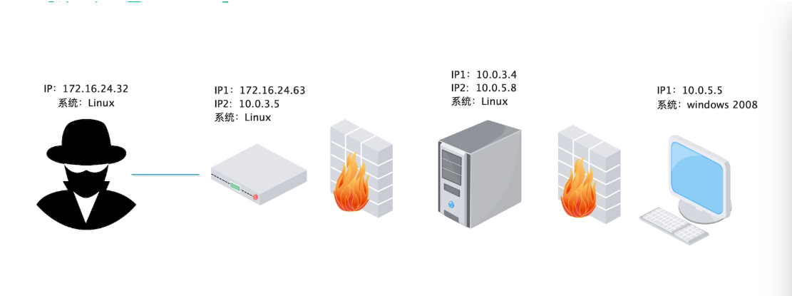
随着网络安全意识的增强,渗透测试成为评估系统安全的关键环节。靶机环境作为渗透测试的基础平台,其搭建和管理对于测试的有效性和安全性至关重要。本文全面概述了渗透测试的基本概念及其对靶机环境的依赖性,深入探讨了靶机环境搭建的理论基础和实践技巧,强调了在选择操作系统、工具、网络配置及维护管理方面的重要性。文章还详细介绍了渗透测试中的攻击模拟、日志分析以及靶机环境的安全加固与风险管理。最后,展
LGO脚本编写:自动化与自定义工作的第一步
# 摘要
本文详细介绍了LGO脚本编写的基础知识和高级应用,探讨了其在自动化任务、数据处理和系统交互中的实战应用。首先概述了LGO脚本的基本元素,包括语法结构、控制流程和函数使用。随后,文章通过实例演练展示了LGO脚本在自动化流程实现、文件数据处理以及环境配置中的具体应用。此外,本文还深入分析了LGO脚本的扩展功能、性能优化以及安全机制,提出了
百万QPS网络架构设计:字节跳动的QUIC案例研究
# 摘要
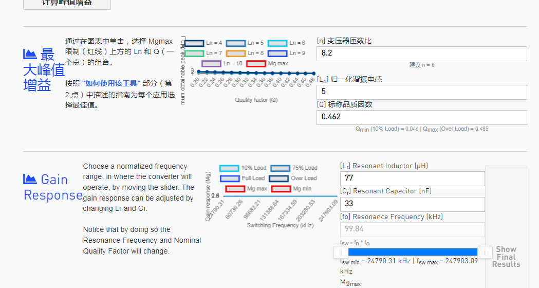
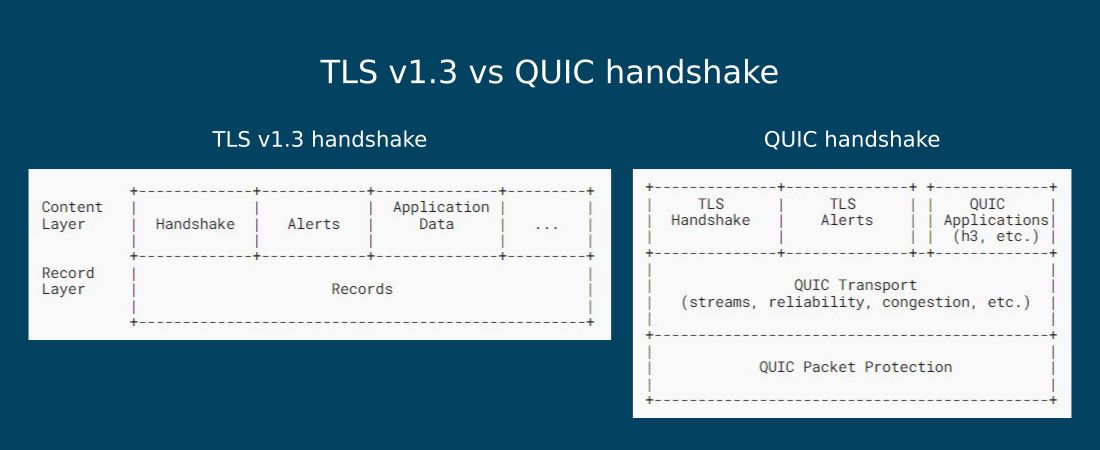
随着网络技术的快速发展,百万QPS(每秒查询数)已成为衡量现代网络架构性能的关键指标之一。本文重点探讨了网络架构设计中面临百万QPS挑战时的策略,并详细分析了QUIC协议作为新兴传输层协议相较于传统TCP/IP的优势,以及字节跳动如何实现并优化QUIC以提升网络性能。通过案例研究,本文展示了QUIC协议在实际应用中的效果,
FPGA与高速串行通信:打造高效稳定的码流接收器(专家级设计教程)

# 摘要
本文全面探讨了基于FPGA的高速串行通信技术,从硬件选择、设计实现到码流接收器的实现与测试部署。文中首先介绍了FPGA与高速串行通信的基础知识,然后详细阐述了FPGA硬件设计的关键步骤,包括芯片选择、硬件配置、高速串行标准选择、内部逻辑设计及其优化。接下来,文章着重讲述了高速串行码流接收器的设计原理、性能评估与优化策略,以及如何在实际应用中进行测试和部署。最后,本文展望了高速串行
Web前端设计师的福音:贝塞尔曲线实现流畅互动的秘密

# 摘要
贝塞尔曲线是计算机图形学中用于描述光滑曲线的重要工具,它在Web前端设计中尤为重要,通过CSS和SVG技术实现了丰富的视觉效果和动画。本文首先介绍了贝塞尔曲线的数学基础和不同类型的曲线,然后具体探讨了如何在Web前端应用中使用贝塞尔曲线,包括CSS动画和SVG路径数据的利用。文章接着通过实践案例分析,阐述了贝塞尔曲线在提升用户界面动效平滑性、交互式动画设计等方面的应用。最后,文章聚焦于性能优化
【终端工具对决】:MobaXterm vs. WindTerm vs. xshell深度比较
# 摘要
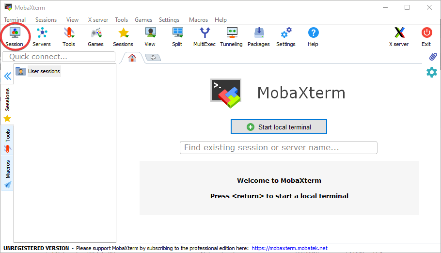
本文对市面上流行的几种终端工具进行了全面的深度剖析,比较了MobaXterm、WindTerm和Xshell这三款工具的基本功能、高级特性,并进行了性能测试与案例分析。文中概述了各终端工具的界面操作体验、支持的协议与特性,以及各自的高级功能如X服务器支持、插件系统、脚本化能力等。性能测试结果和实际使用案例为用户提供了具体的性能与稳定性数据参考。最后一章从用户界面、功能特性、性能稳定性等维度对
电子建设项目决策系统:预算编制与分析的深度解析

# 摘要
本文对电子建设项目决策系统进行了全面的概述,涵盖了预算编制和分析的核心理论与实践操作,并探讨了系统的优化与发展方向。通过分析预算编制的基础理论、实际项目案例以及预算编制的工具和软件,本文提供了深入的实践指导。同时,本文还对预算分析的重要性、方法、工具和实际案例进行了详细讨论,并探讨了如何将预算分析结果应用于项目优化。最后,本文考察了电子建设项目决策系统当前的优化方法和未来的发展趋势
【CSEc硬件加密模块集成攻略】:在gcc中实现安全与效率
# 摘要
本文详细介绍了CSEc硬件加密模块的基础知识、工作原理、集成实践步骤、性能优化与安全策略以及在不同场景下的应用案例。首先,文章概述了CSEc模块的硬件架构和加密解密机制,并将其与软件加密技术进行了对比分析。随后,详细描述了在gcc环境中如何搭建和配置环境,并集成CSEc模块到项目中。此外,本文还探讨了性能调优和安全性加强措施,包括密钥管理和防御
【确保硬件稳定性与寿命】:硬件可靠性工程的实战技巧

# 摘要
硬件可靠性工程是确保现代电子系统稳定运行的关键学科。本文首先介绍了硬件可靠性工程的基本概念和硬件测试的重要性,探讨了不同类型的硬件测试方法及其理论基础。接着,文章深入分析了硬件故障的根本原因,故障诊断技术,以及预防性维护对延长设备寿命的作用。第四章聚焦于硬件设计的可靠性考虑,HALT与HAS
资源上传下载、课程学习等过程中有任何疑问或建议,欢迎提出宝贵意见哦~我们会及时处理!
点击此处反馈


专栏目录
最低0.47元/天 解锁专栏
买1年送3月
百万级
高质量VIP文章无限畅学
千万级
优质资源任意下载
C知道
免费提问 ( 生成式Al产品 )