10
11
12
13
14
15
16
0 10 20 30 40 50
Input Referred Noise Current,
pA rms in 5Hz Bandwidth
Pleth Current (A)
Duty cycle 1%
Duty cycle 5%
Duty cycle 10%
Duty cycle 15%
Duty cycle 20%
Duty cycle 25%
For each setting RF adjusted for Full-Scale Output.
Amb Cancellation & stage 2 Gain = 4 used for Low pleth currents (0.125uA, 0.25uA & 0.5uA.)
RMS noise is calculated in 5Hz B/W & NFB is calculated using 6.6 u RMS noise.
10
11
12
13
14
15
16
0 10 20 30 40 50
Input Referred Noise Current,
pA rms in 5Hz Bandwidth
Pleth Current (A)
Duty cycle 1%
Duty cycle 5%
Duty cycle 10%
Duty cycle 15%
Duty cycle 20%
Duty cycle 25%
For each setting RF adjusted for Full-Scale Output.
Amb Cancellation & stage 2 Gain = 4 used for Low Pleth currents (0.125uA, 0.25uA & 0.5uA).
RMS noise is calculated in 5Hz B/W & NFB is calculated using 6.6 u RMS noise.
0
200
400
600
800
1000
1200
1400
1600
1800
2000
0 10 20 30 40 50
Input Referred Noise Current,
pA rms in 5Hz Bandwidth
Pleth Current (A)
Duty cycle 1%
Duty cycle 5%
Duty cycle 10%
Duty cycle 15%
Duty cycle 20%
Duty cycle 25%
For each setting RF adjusted for Full-Scale Output.
Amb Cancellation & stage 2 Gain = 4 used for
Low Pleth currents (0.125uA, 0.25uA & 0.5uA).
Noise is calculated in 5Hz band.
10
11
12
13
14
15
16
0 10 20 30 40 50
Input Referred Noise Current,
pA rms in 5Hz Bandwidth
Pleth Current (A)
Duty cycle 1%
Duty cycle 5%
Duty cycle 10%
Duty cycle 15%
Duty cycle 20%
Duty cycle 25%
For each setting RF adjusted for Full-Scale Output.
Amb Cancellation & stage 2 Gain = 4 used for Low Pleth currents (0.125uA, 0.25uA & 0.5uA).
RMS noise is calculated in 5Hz B/W & NFB is calculated using 6.6 u RMS noise.
0
200
400
600
800
1,000
1,200
0 10 20 30 40 50
Input Referred Noise Current,
pA rms in 5Hz Bandwidth
Pleth Current (A)
Duty Cycle = 1%
Duty Cycle = 5%
Duty Cycle = 10%
Duty Cycle = 15%
Duty Cycle = 20%
Duty Cycle = 25%
For each RF adjusted for Full-Scale Output.
Amb Cancellation & stage 2 Gain = 4 used for Low
Pleth currents (0.125uA, 0.25uA & 0.5uA).
Noise is calculated in 5Hz band.
0
200
400
600
800
1000
1200
1400
1600
1800
2000
0 10 20 30 40 50
Input Referred Noise Current,
pA rms in 5Hz Bandwidth
Pleth Current (A)
Duty cycle 1%
Duty cycle 5%
Duty cycle 10%
Duty cycle 15%
Duty cycle 20%
Duty cycle 25%
For each setting RF adjusted for Full-Scale Output.
Amb Cancellation & stage 2 Gain = 4 used for
Low Pleth currents (0.125uA, 0.25uA & 0.5uA).
Noise is calculated in 5Hz band.
AFE4400
www.ti.com.cn
ZHCSBO2H –DECEMBER 2012–REVISED JULY 2014
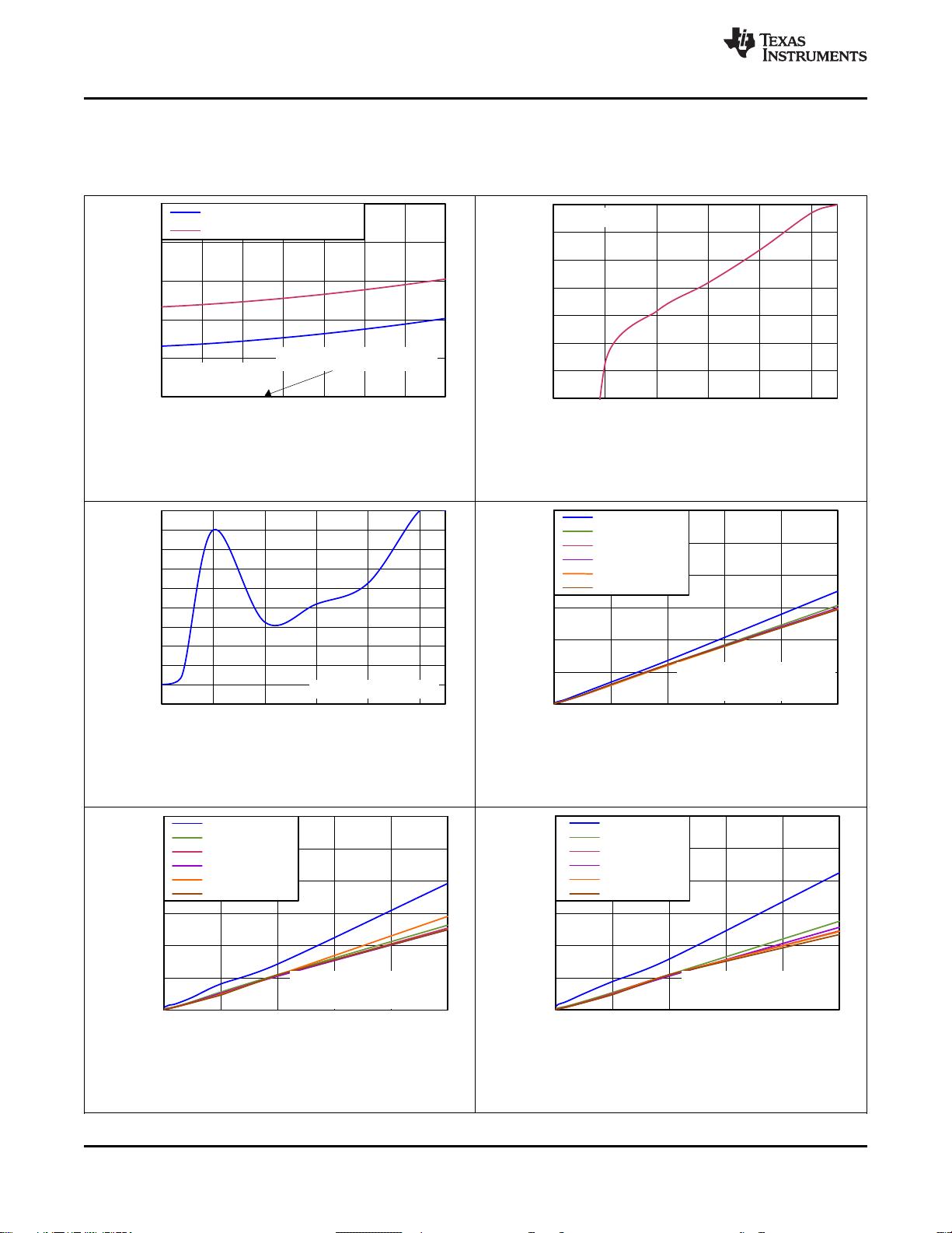
Typical Characteristics (continued)
Minimum and maximum specifications are at T
A
= 0°C to 70°C. Typical specifications are at T
A
= 25°C, RX_ANA_SUP =
RX_DIG_SUP = 3.0 V, TX_CTRL_SUP = LED_DRV_SUP = 3.3 V, and f
CLK
= 8 MHz, unless otherwise noted.
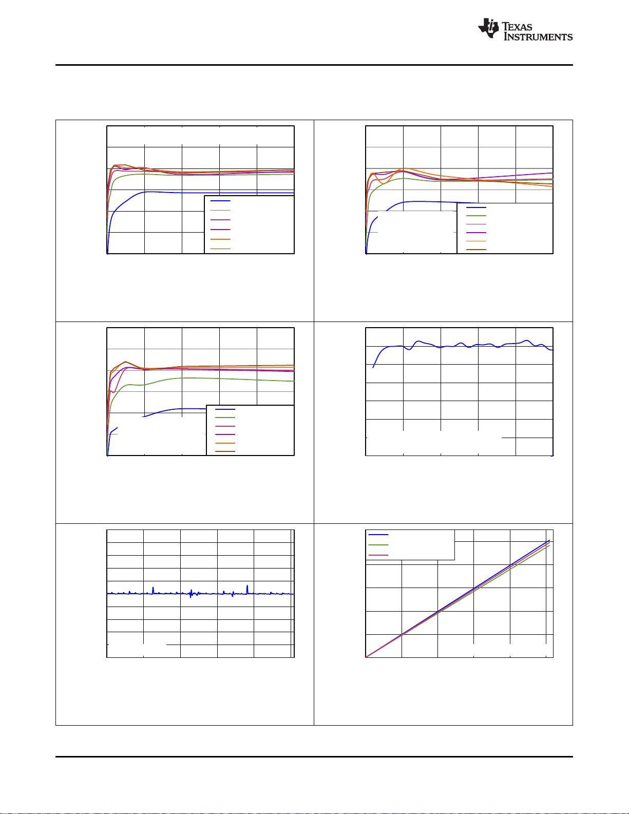
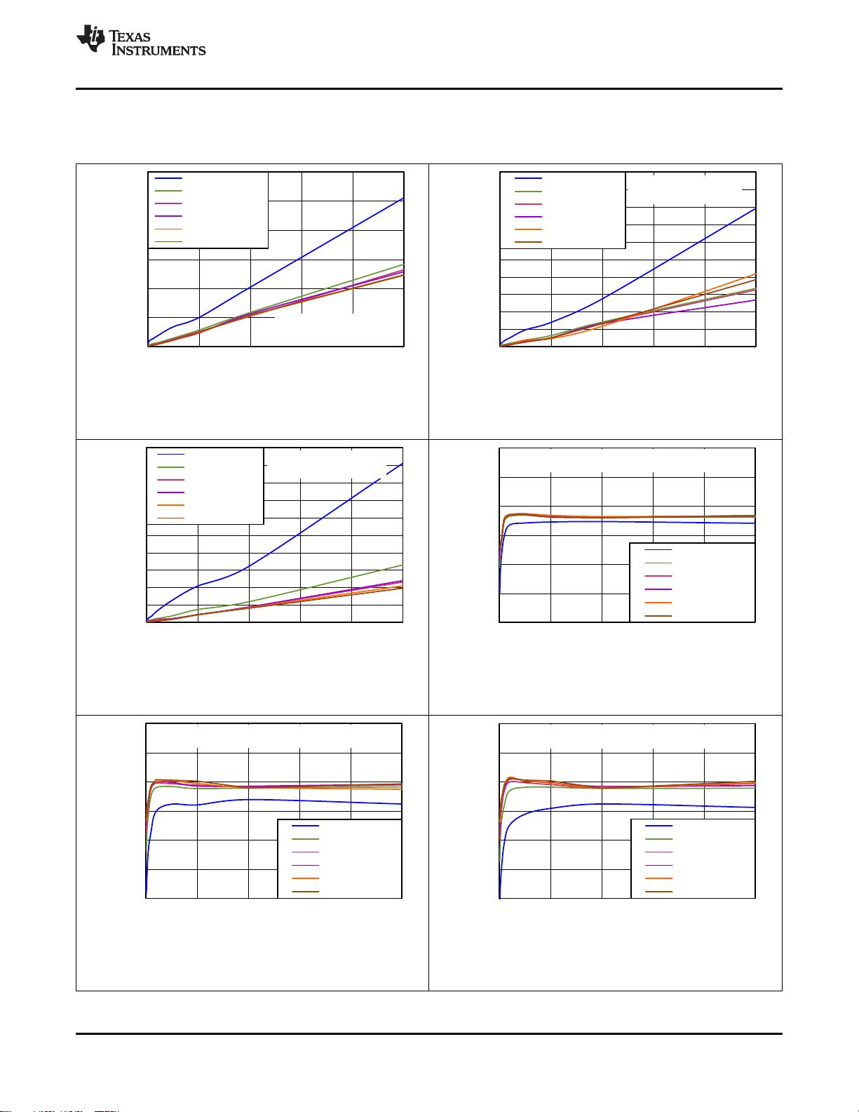
Figure 11. Input-Referred Noise Current vs Figure 12. Input-Referred Noise Current vs
Pleth Current (PRF = 1200 Hz) Pleth Current (PRF = 2500 Hz)
Figure 13. Input-Referred Noise Current vs Figure 14. Noise-Free Bits vs Pleth Current
Pleth Current (PRF = 5000 Hz) (PRF = 100 Hz)
Figure 15. Noise-Free Bits vs Pleth Current Figure 16. Noise-Free Bits vs Pleth Current
(PRF = 300 Hz) (PRF = 600 Hz)
Copyright © 2012–2014, Texas Instruments Incorporated 17