
encapsulated with an address field including the source
wireless router address (SWRA), destination segment
address (DSA), and destination IP address (DIPA). Here,
the SWRA, DSA, and DIPA identify the source wireless
router, destination OLT, and destination core router, re-
spectively. When the traffic is transferred from the failed
segments into the backup segments, the DSA of the data
packets will be reset according to the backup segments.
However, their SWRA and DIPA remain unchanged.
Therefore, although the destination OLTs are changed,
these data packets could still be delivered to the original
destination core routers, so that the traffic connections
of the failed segments are recovered.
B. Why the Lower Deployment Cost for Backup
Fibers
It is worth noting that the CBP scheme allows the failed
segments to transfer their traffic into any other normal seg-
ments in the same cluster, including not only the neighbor
segments but also the remote segments. Therefore, the CBP
scheme can utilize the backup fibers more efficiently and
thus requires a lower deployment cost for backup fibers than
the previous works [
9,10], in which the failed segment can
transfer its traffic into only the normal neighbor segments.
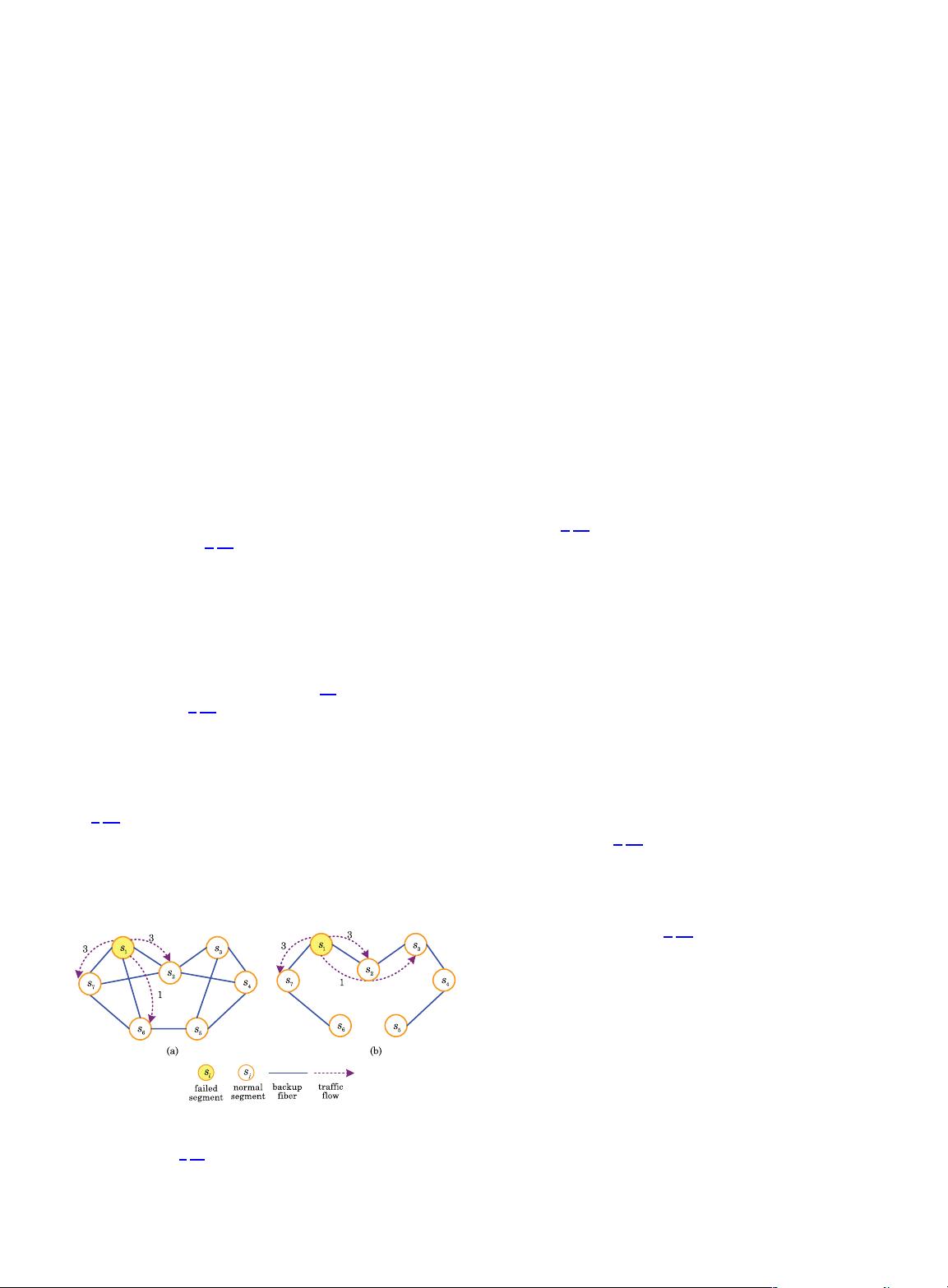
We illustrate this in Fig. 3. It shows a cluster of seven
segments s
1
, s
2
, s
3
, s
4
, s
5
, s
6
,ands
7
, and each segment is
assumed to have 10 units of capacity. For simplicity, we
further assume that all segments equally have 7 units of
traffic demand and thus 3 units of residual capacity (where
each unit of traffic demand denotes the demand for a certain
amount of bandwidth capacity (Mb/s) [
14]). Because the pro-
tection scheme in [
9,10] can tolerate only single segment fail-
ure, we consider single segment failure in this illustration.
Therefore, any pair of segments can share the same unit of
residual capacity for backup. In order to fully protect all the
traffic demand in the network, each segment needs at least
three backup segments. According to the protection scheme
in [
9,10], only the neighbor segments are used as backup
segments. Thus, for any one segment s
i
, the backup fibers
should be deployed between s
i
and each one of its backup
segments. As a result, 11 backup fibers need to be deployed,
as shown in Fig. 3(a). Once any segment s
1
fails, the traffic
demand in s
1
will be transferred into the neighbor segments
s
2
, s
6
,ands
7
along the backup fibers between them. There-
after, s
2
, s
6
,ands
7
carry 3, 1, and 3 units of traffic demand
from s
1
by using their residual capacity, respectively. How-
ever, according to our CBP scheme in Fig. 3(b), the failed seg-
ment is allowed to transfer its traffic into not only the
neighbor segments but also the remote segments. In this
case, it is not necessary to deploy the backup fibers between
any segment s
i
and each one of its backup segments. In-
stead, we only need to deploy 6 backup fibers to establish
at least one backup optical path between each pair of seg-
ments among s
1
, s
2
, s
3
, s
4
, s
5
, s
6
,ands
7
. When any segment
s
1
fails, s
1
can transfer 3, 3, and 1 unit of traffic demand into
s
2
along the backup fiber between s
1
and s
2
,intos
7
along the
backup fiber between s
1
and s
7
,andintos
3
along the backup
optical path (s
1
–s
2
–s
3
), respectively. It is worth mentioning
that s
2
forwards the traffic demand of s
1
to s
3
by utilizing the
bandwidth of the backup fiber between s
2
and s
3
instead of
the residual capacity of s
2
. Thus, the traffic demand that s
2
can forward to s
3
is not limited by the residual capacity of s
2
.
Compared to Fig. 3(a), the backup fibers are utilized more
efficiently in Fig. 3(b), e.g., the backup fiber between s
1
and s
2
. Therefore, our CBP scheme requires fewer backup
fibers and thus a lower deployment cost than the protection
scheme in [
9,10].
C. Why Stronger Network Survivability
According to our CBP scheme, there exists at least one
backup optical path between any pair of segments in the
same cluster. Therefore, the failed segments can transfer
their traffic into any other normal segments in the same
cluster, which enables the CBP scheme to tolerate the
simultaneous failures of X segments. For example, in
Fig. 3(b), when s
1
and s
7
fail simultaneously (i.e., X 2),
they can transfer their traffic into any one of s
2
, s
3
, s
4
,
s
5
, and s
6
along the backup optical paths between them.
In this case, s
1
and s
7
will be fully protected because s
2
,
s
3
, s
4
, s
5
, and s
6
have enough total residual capacity to
carry the traffic of s
1
and s
7
. However, in Fig. 3(a), the pro-
tection scheme in [
9,10] cannot tolerate the simultaneous
failures of s
1
and s
7
because the residual capacity of their
neighbor segments s
2
and s
6
is not enough to carry the
traffic of s
1
and s
7
for full protection. Therefore, our CBP
scheme can protect FiWi with stronger survivability than
the protection scheme in [
9,10].
D. How to Deal With Performance Loss
It may be noted that if the backup optical path is longer
(measured in number of hops), the failed segment will suffer
from a longer recovery time for transferring its traffic as well
as worse optical signal quality. For this consideration, we in-
troduce the constraint of available backup optical path into
our CBP scheme to deal with its performance loss in the re-
covery time and optical signal quality. The available backup
optical path refers to a backup optical path whose length is
less than or equal to ABC hops. In any one cluster, a failed
segment can transfer its traffic into another normal segment
Fig. 3. Comparison of the backup fiber deployment between the
previous scheme [
9,10] and our CBP scheme: (a) only neighbor
segments are used for backup and (b) both neighbor segments
and remote segments are used for backup.
Guo et al. VOL. 5, NO. 11/NOVEMBER 2013/J. OPT. COMMUN. NETW. 1181
剩余16页未读,继续阅读

weixin_38641876
- 粉丝: 3
- 资源: 942
 我的内容管理
展开
我的内容管理
展开


最新资源
- 构建Cadence PSpice仿真模型库教程
- VMware 10.0安装指南:步骤详解与网络、文件共享解决方案
- 中国互联网20周年必读:影响行业的100本经典书籍
- SQL Server 2000 Analysis Services的经典MDX查询示例
- VC6.0 MFC操作Excel教程:亲测Win7下的应用与保存技巧
- 使用Python NetworkX处理网络图
- 科技驱动:计算机控制技术的革新与应用
- MF-1型机器人硬件与robobasic编程详解
- ADC性能指标解析:超越位数、SNR和谐波
- 通用示波器改造为逻辑分析仪:0-1字符显示与电路设计
- C++实现TCP控制台客户端
- SOA架构下ESB在卷烟厂的信息整合与决策支持
- 三维人脸识别:技术进展与应用解析
- 单张人脸图像的眼镜边框自动去除方法
- C语言绘制图形:余弦曲线与正弦函数示例
- Matlab 文件操作入门:fopen、fclose、fprintf、fscanf 等函数使用详解
资源上传下载、课程学习等过程中有任何疑问或建议,欢迎提出宝贵意见哦~我们会及时处理!
点击此处反馈


