
2
On-Chip Peripheral Bus Version 2.1
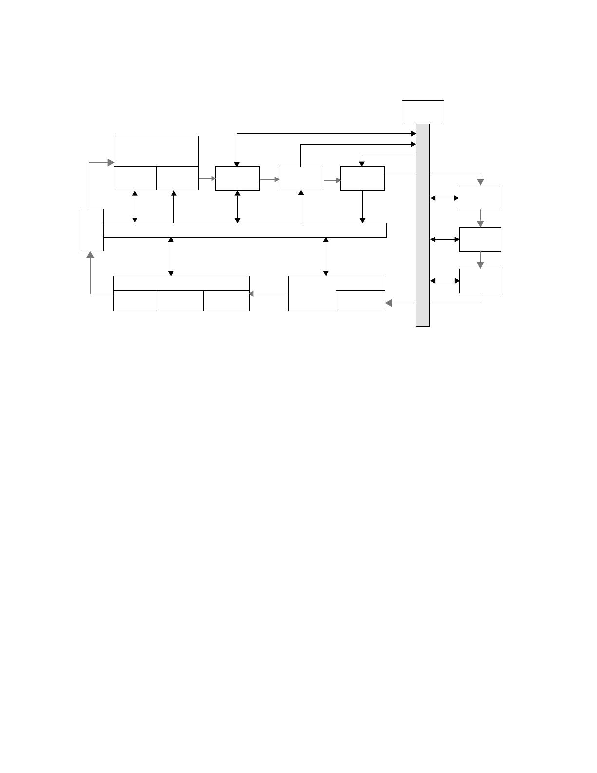
Figure 1 demonstrates how the on-chip peripheral bus is interconnected for the purpose of
Core+ASIC development or system-on-a-chip design.
As shown in Figure 1, the on-chip bus structure provides a link between the processor core and other
peripherals which consist of PLB and OPB master and slave devices.
The processor local bus (PLB) is the high performance bus used to access memory through the bus
interface units. The two bus interface units shown above: external peripheral controller and memory
controller are the PLB slaves. The processor core has two PLB master connections, one for
instruction cache and one for data cache. Attached to the PLB is also the direct memory access
(DMA) controller, which is a PLB master device used in data intensive applications to improve data
transfer performance.
Lower performance peripherals (such as OPB master, slave, and other internal peripherals) are
attached to the on-chip peripheral bus (OPB). A bridge is provided between the PLB and OPB to
enable data transfer by PLB masters to and from OPB slaves. The PLB to OPB bridge is a slave on
the PLB and a master on the OPB. A bridge is provided between the OPB and PLB to enable data
transfer by OPB masters to and from PLB slaves. The OPB to PLB bridge is a slave on the OPB and
a master on the PLB. DMA slave peripherals are also supported on the OPB.
The device control register (DCR) bus is used primarily for accessing status and control registers
within the various PLB and OPB masters and slaves. It is meant to off-load the PLB from the lower
performance status and control register read and write transfers. The DCR bus architecture allows
data transfers to occur independent of PLB and OPB transfers.
On-Chip Peripheral Bus
Processor Local Bus
OPB
PLB
OPB
Internal
OPB
Master
Slave
Peripheral
PLB to OPB
Bridge
Figure 1. On-chip Peripheral Bus Interconnection
DCR Bus
DCR Bus
Arbiter
Arbiter
Processor Core
Data Instruction
Cache UnitCache Unit
OPB to PLB
Bridge
Memory Controller
SDRAM
Controller
External Peripheral Controller
External
Peripheral
External
Bus Master
DMA
Controller
DCR Bus
SRAM
ROM
DCR Bus


剩余117页未读,继续阅读

ppcust
- 粉丝: 38
- 资源: 725
 我的内容管理
展开
我的内容管理
展开


最新资源
- 多模态联合稀疏表示在视频目标跟踪中的应用
- Kubernetes资源管控与Gardener开源软件实践解析
- MPI集群监控与负载平衡策略
- 自动化PHP安全漏洞检测:静态代码分析与数据流方法
- 青苔数据CEO程永:技术生态与阿里云开放创新
- 制造业转型: HyperX引领企业上云策略
- 赵维五分享:航空工业电子采购上云实战与运维策略
- 单片机控制的LED点阵显示屏设计及其实现
- 驻云科技李俊涛:AI驱动的云上服务新趋势与挑战
- 6LoWPAN物联网边界路由器:设计与实现
- 猩便利工程师仲小玉:Terraform云资源管理最佳实践与团队协作
- 类差分度改进的互信息特征选择提升文本分类性能
- VERITAS与阿里云合作的混合云转型与数据保护方案
- 云制造中的生产线仿真模型设计与虚拟化研究
- 汪洋在PostgresChina2018分享:高可用 PostgreSQL 工具与架构设计
- 2018 PostgresChina大会:阿里云时空引擎Ganos在PostgreSQL中的创新应用与多模型存储
资源上传下载、课程学习等过程中有任何疑问或建议,欢迎提出宝贵意见哦~我们会及时处理!
点击此处反馈


