
SN75DP120
SLLSE08 –OCTOBER 2009
www.ti.com
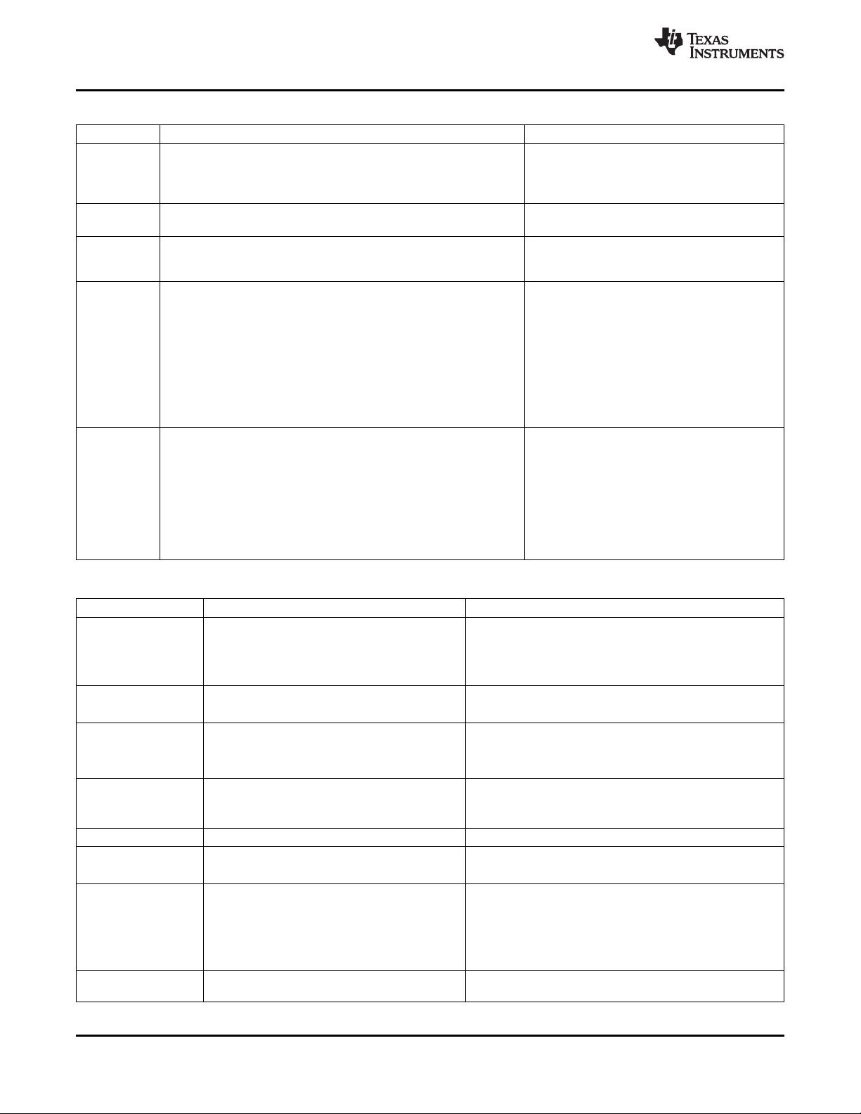
Table 1. Description of SN75DP120 Modes
MODE CHARACTERISTICS CONDITIONS
ShutDown Least amount of power consumption (most circuitry turned off); LP# is low
Mode
HPD_SRC reflects HPD_SINK state, all other outputs are high
impedance and all other inputs are ignored.
DPCD registers and logic are held reset to default values
Standby Mode Low power consumption; main link inputs and outputs are disabled, LP# is high;
AUX monitoring is enabled HPD_SINK low for longer than t
T(HPD)
D3 Power Low power consumption; main link inputs and outputs disabled, LP# is high;
Down Mode
AUX monitoring is enabled AUX command requested DP sink to enter D3
power saving mode
Active Mode Data transfer (normal operation); LP# is high;
The device is either in TMDS mode (CAD_SINK=high) or DP mode HPD_SINK is high
(CAD_SINK=low);
HPD_SINK can also be low for less than t
T(HPD)
(e.g. sink interrupt request to source)
In DP mode, the AUX monitor is actively monitoring for link training,
Link Training has begun or completed
and the output signal swing, input equalization level and lane count
depend on the link training. At power-up all main link outputs are
disabled by default. AUX Link training is necessary to overwrite the
DPCD registers to enable main link outputs.
In TMDS mode, the output signal swing will be 600mVp-p, and
transactions on the AUX lines will be ignored.
Output Disable DPCD write commands on the AUX bus detected by the SN75DP120 EN is high
Mode will also write to the local DP120 DPCD register. The local DPCD
DPCD register 101h or 103h entry is invalid
registers should always be written with valid entries. If register 101h or
103h is written with an invalid value, the SN75DP120 disables the
OUTx main link output signals, forcing the DP sink to issue an
interrupt. The DP source can now re-train the link using valid DPCD
register values. As soon as all DPCD registers contain a valid entry,
the SN75DP120 switches back into the appropriate mode of operation.
For a list of valid and invalid DPCD register entries refer to Table 3 and
the DP1.1a specification Table 2-52 and Table 3-12.
Table 2. Transition Between Operational Modes
MODE TRANSITION USE CASE TRANSITION SPECIFICS
Shutdown → Standby Activate DP120 1. LP# transitions from low to high
2. Receiver enters Standby mode
3. AUX listener turns on and begins to monitor the AUX
lines
Standby → Active Turn on main link (monitor plugged in) 1. HPD_SINK input asserts high
2. Main link outputs turn on
Active → D3 DP source requests temporary power down for 1. Receive D3 entry command on AUX
power savings
2. Main link inputs and outputs are disabled
3. AUX monitor remains active
D3 → Active Exit temporary power down 1. AUX channel receives D3 exit command or HPD_SINK
transitions from low to high
2. Enable main link
D3 → Standby Exit temporary power down 1. HPD_SINK de-asserted to low for longer than t
T(HPD)
Active → Standby turn off main link (monitor unplugged) 1. HPD_SINK de-asserted for longer than t
T(HPD)
2. Main link inputs and outputs are disabled
Active/Standby → Turn off DP120 1. LP# pulled low
Shutdown
2. AUX, Main link inputs and outputs are disabled
3. Most IC circuitry is shut down for ultra low power
consumption
4. HPD_SRC reflects HPD_SINK
Any State → Output Invalid DPCD write value to register 101h or 103h 1. OUTx becomes disabled
Disable Mode
6 Submit Documentation Feedback Copyright © 2009, Texas Instruments Incorporated
Product Folder Link(s): SN75DP120
剩余28页未读,继续阅读


