
MP4027 – PRIMARY-SIDE CONTROL, OFFLINE LED CONTROLLER WITH ACTIVE PFC
MP4027 Rev. 1.02 www.MonolithicPower.com 4
12/9/2014 MPS Proprietary Information. Patent Protected. Unauthorized Photocopy and Duplication Prohibited.
© 2014 MPS. All Rights Reserved.
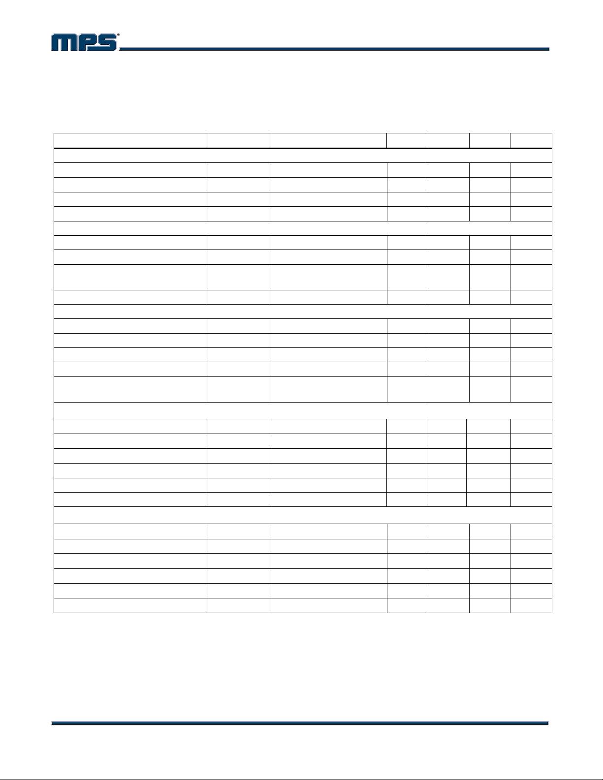
ELECTRICAL CHARACTERISTICS
Typical values are at VCC = 20V, T
J
= +25°C, unless otherwise noted.
Minimum and maximum values are at VCC = 20V, T
J
= -40°C to +125°C, unless otherwise noted,
guaranteed by characterization.
Parameter Symbol Condition Min Typ Max Units
Supply Voltage
Operating Range VCC After turn on 12 28 V
Turn-On Threshold VCC
ON
VCC rising edge 23.0 25.5 28.0 V
Turn-Off Threshold VCC
OFF
VCC falling edge 8.4 9.5 11.0 V
Hysteretic Voltage VCC
HYS
14.2 15.7 17.3 V
Supply Current
Start-Up Current I
STARTUP
VCC= VCC
ON
-1V 20 50 µA
Quiescent Current I
Q
No switching 0.6 0.82 mA
Operating Current Under Fault
Condition
No switching 2 mA
Operating Current I
CC
f
s
=70kHz, C
GATE
=1nF 2 3 mA
Multiplier
Linear Operation Range V
MULT
0 3 V
Gain K
(5)
1.3 1/V
Brown-Out Protection Threshold 280 298 316 mV
Brown-Out Detection Time 25 42 60 ms
Brown-Out Protection Hysteretic
Voltage
90 100 110 mV
NTC
High-Threshold Voltage V
H_NTC
1.17 1.23 1.29 V
Low-Threshold Voltage V
L_NTC
0.67 0.77 0.87 V
Shutdown Threshold V
SD_NTC
0.355 0.39 0.425 V
Shutdown-Voltage Hysteretic
85 100 115 mV
Pull-Up Current Source I
PULL_UP
44 54 64 μA
Leakage Current I
LEAKAGE
1 μA
Error Amplifier
Reference Voltage V
REF
0.401 0.413 0.425 V
Transconductance
(6)
G
EA
125 µA/V
Upper Clamp Voltage V
COMP_H
4.5 4.75 5.1 V
Lower Clamp Voltage V
COMP_L
1.42 1.5 1.58 V
Max. Source Current
(6)
I
COMP_SOURCE
50 µA
Max. Sink Current
(6)
I
COMP_SINK
-200 µA
剩余18页未读,继续阅读

qq_41402004
- 粉丝: 0
- 资源: 1
 我的内容管理
收起
我的内容管理
收起
- 我的资源
快来上传第一个资源
 我的收益 登录查看自己的收益
 我的积分
登录查看自己的积分
我的积分
登录查看自己的积分
 我的C币
登录后查看C币余额
我的C币
登录后查看C币余额
 我的收藏
我的收藏  我的下载
我的下载  下载帮助
下载帮助

会员权益专享


最新资源
- 京瓷TASKalfa系列维修手册:安全与操作指南
- 小波变换在视频压缩中的应用
- Microsoft OfficeXP详解:WordXP、ExcelXP和PowerPointXP
- 雀巢在线媒介投放策划:门户网站与广告效果分析
- 用友NC-V56供应链功能升级详解(84页)
- 计算机病毒与防御策略探索
- 企业网NAT技术实践:2022年部署互联网出口策略
- 软件测试面试必备:概念、原则与常见问题解析
- 2022年Windows IIS服务器内外网配置详解与Serv-U FTP服务器安装
- 中国联通:企业级ICT转型与创新实践
- C#图形图像编程深入解析:GDI+与多媒体应用
- Xilinx AXI Interconnect v2.1用户指南
- DIY编程电缆全攻略:接口类型与自制指南
- 电脑维护与硬盘数据恢复指南
- 计算机网络技术专业剖析:人才培养与改革
- 量化多因子指数增强策略:微观视角的实证分析
资源上传下载、课程学习等过程中有任何疑问或建议,欢迎提出宝贵意见哦~我们会及时处理!
点击此处反馈


