

Quartus
®
II Introduction for Verilog Users
This tutorial presents an introduction to the Quartus
®
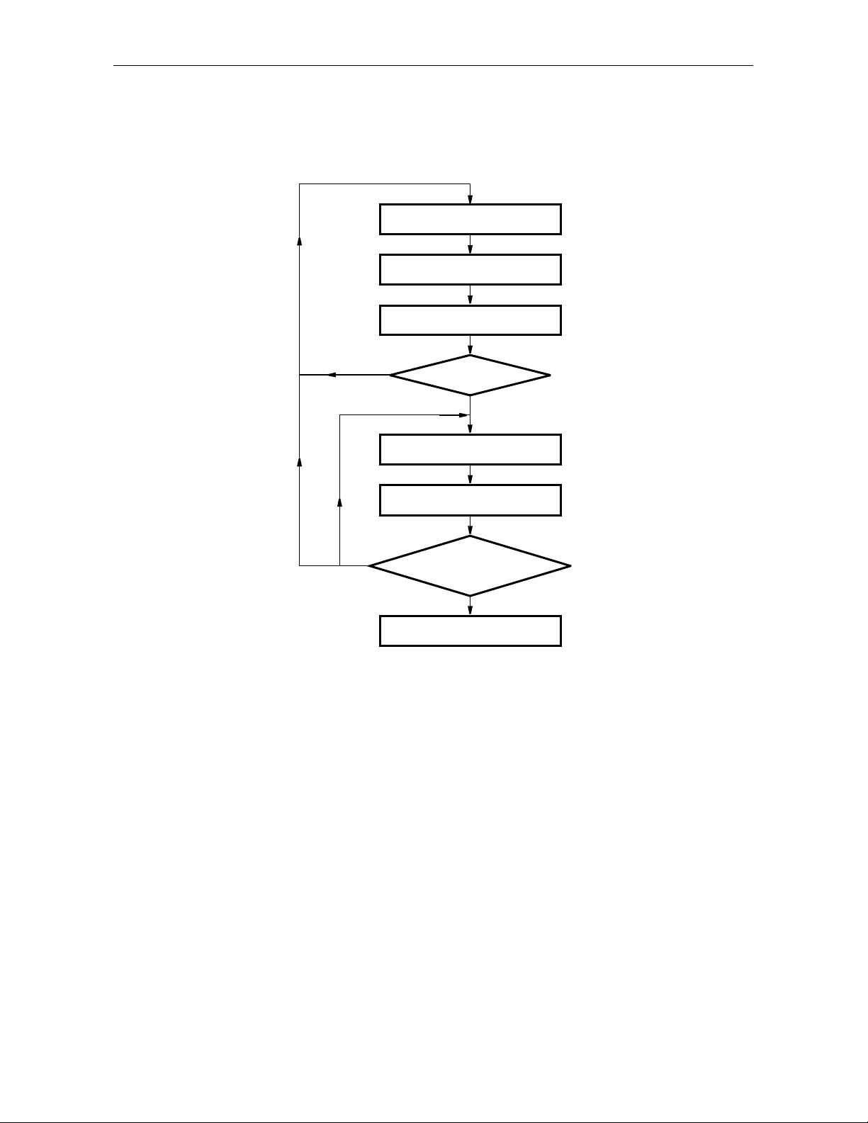
II software. It gives a general overview of a typical CAD
flow for designing circuits that are implemented by using FPGA devices, and shows how this flow is realized in the
Quartus
®
II software. The design process is illustrated by giving step-by-step instructions for using the Quartus
®
II software to implement a simple circuit in an Altera
®
FPGA device.
The Quartus
®
II system includes full support for all of the popular methods of entering a description of the
desired circuit into a CAD system. This tutorial makes use of the Verilog design entry method, in which the
user specifies the desired circuit in the Verilog hardware description language. Another version of this tutorial is
available that uses VHDL hardware description language.
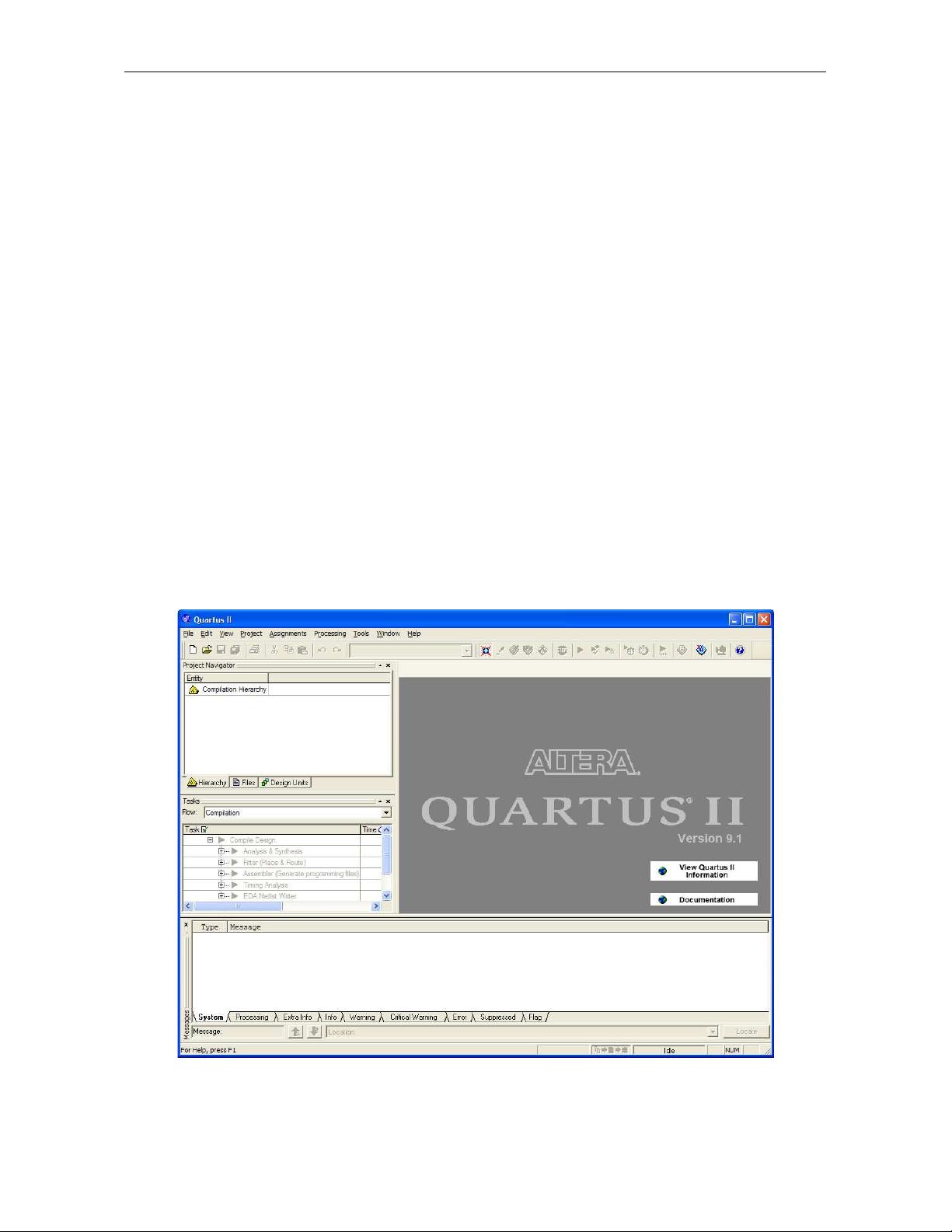
The screen captures in the tutorial were obtained using Quartus
®
II version 9.1; if other versions of the soft-
ware are used, some of the images may be slightly different.
Contents:
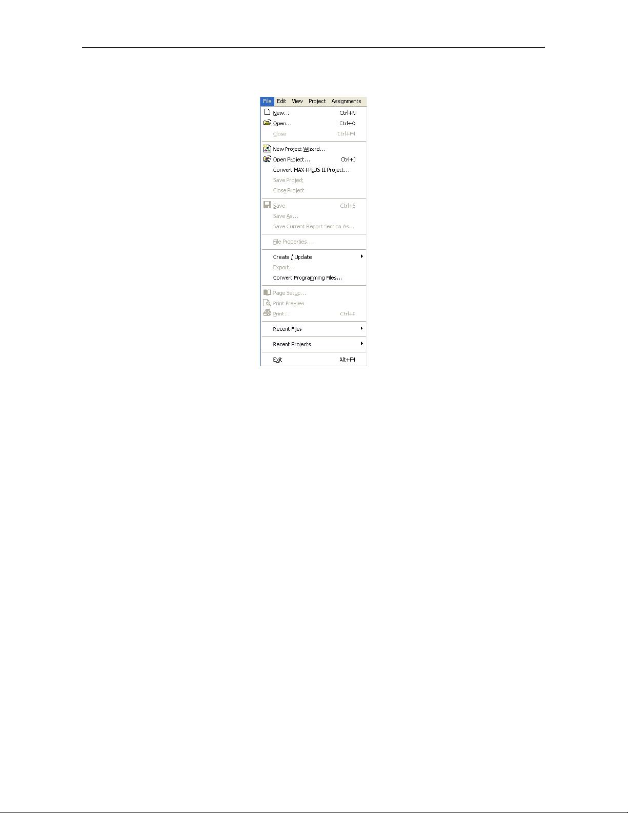
Getting Started
Starting a New Project
Design Entry Using Verilog Code
Compiling the Verilog Code
Using the RTL Viewer
Specifying Timing Constraints
Quartus
®
II Windows

剩余29页未读,继续阅读

竹涛如海
- 粉丝: 0
- 资源: 2
 我的内容管理
收起
我的内容管理
收起
- 我的资源
快来上传第一个资源
 我的收益 登录查看自己的收益
 我的积分
登录查看自己的积分
我的积分
登录查看自己的积分
 我的C币
登录后查看C币余额
我的C币
登录后查看C币余额
 我的收藏
我的收藏  我的下载
我的下载  下载帮助
下载帮助

会员权益专享


最新资源
- 京瓷TASKalfa系列维修手册:安全与操作指南
- 小波变换在视频压缩中的应用
- Microsoft OfficeXP详解:WordXP、ExcelXP和PowerPointXP
- 雀巢在线媒介投放策划:门户网站与广告效果分析
- 用友NC-V56供应链功能升级详解(84页)
- 计算机病毒与防御策略探索
- 企业网NAT技术实践:2022年部署互联网出口策略
- 软件测试面试必备:概念、原则与常见问题解析
- 2022年Windows IIS服务器内外网配置详解与Serv-U FTP服务器安装
- 中国联通:企业级ICT转型与创新实践
- C#图形图像编程深入解析:GDI+与多媒体应用
- Xilinx AXI Interconnect v2.1用户指南
- DIY编程电缆全攻略:接口类型与自制指南
- 电脑维护与硬盘数据恢复指南
- 计算机网络技术专业剖析:人才培养与改革
- 量化多因子指数增强策略:微观视角的实证分析
资源上传下载、课程学习等过程中有任何疑问或建议,欢迎提出宝贵意见哦~我们会及时处理!
点击此处反馈


