没有合适的资源?快使用搜索试试~ 我知道了~
首页NMOS与PMOS LDO的概述
NMOS与PMOS LDO的概述
需积分: 35 24 下载量 147 浏览量
更新于2023-06-22
评论
收藏 519KB PDF 举报
To be able to explain the differences between NMOS and PMOS Linear Voltage Regulators; their basic operation, advantages and limitations, as well as identifing applications where one, or the other, would be appropriate choice.
资源详情
资源评论
资源推荐
NMOS and PMOS Linear Voltage Regulators
Course Objective:
To be able to explain the differences between NMOS and PMOS Linear Voltage Regulators; their basic operation, advantages and limitations, as
well as identifing applications where one, or the other, would be appropriate choice.
Course Map/Table of Contents
1. Course Navigation
1.1 Course Navigation1.
2. Linear Voltage Regulator Basics
2.1 Introduction1.
2.2 The Linear Voltage Regulator2.
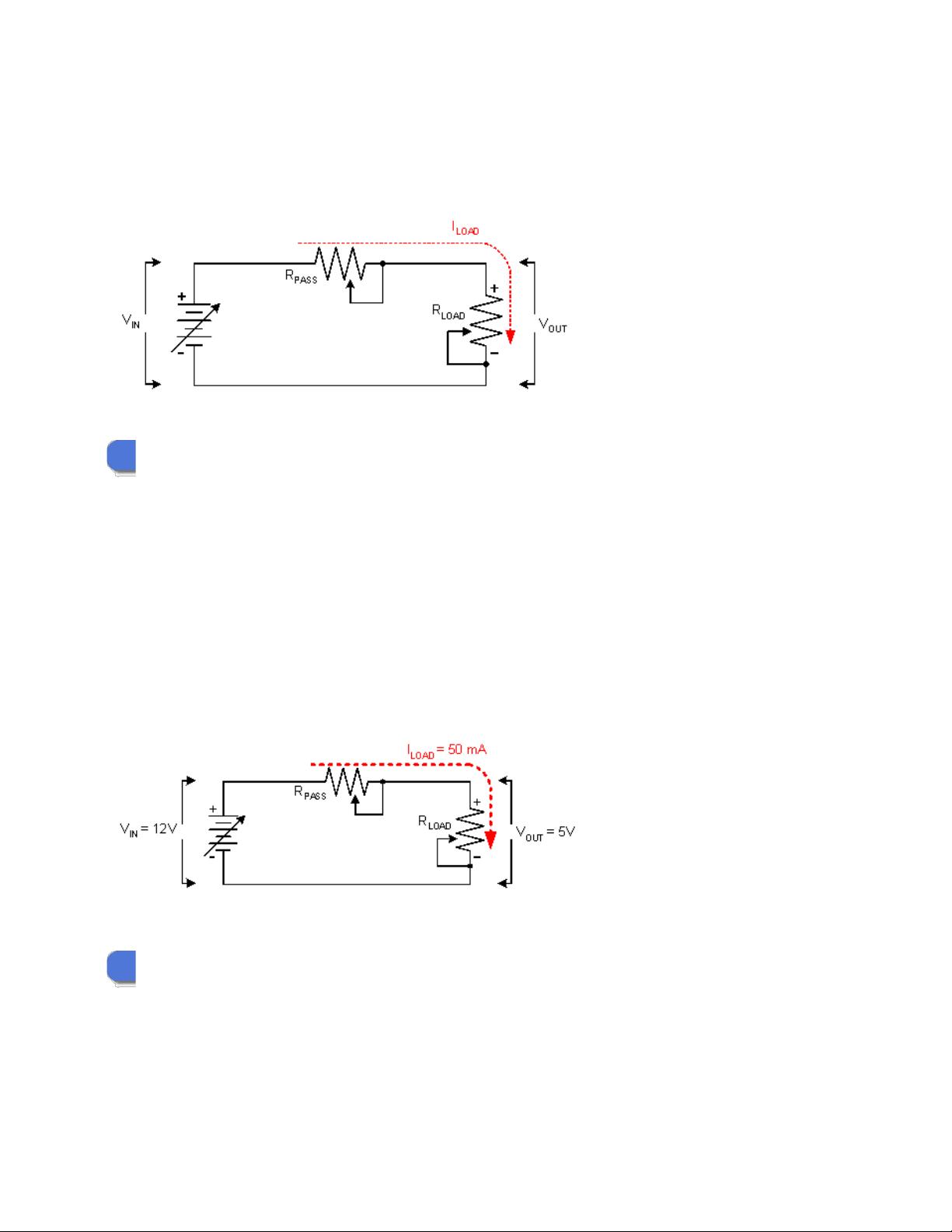
2.3 Simple Model3.
2.4 Simple Model, with variables4.
2.5 Simple Model, with values5.
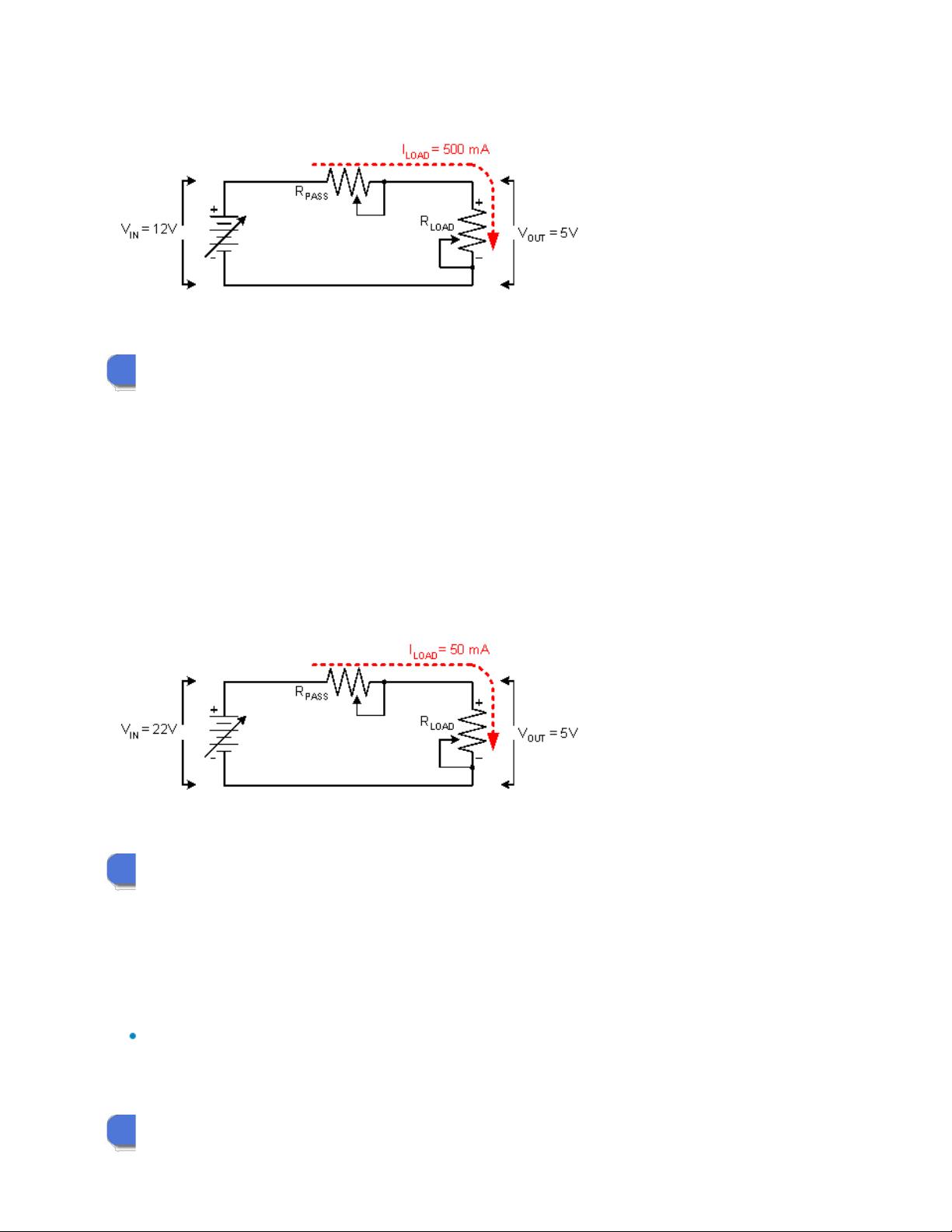
2.6 Simple Model, with a change of Load Current6.
2.7 Simple Model, with a change in Input Voltage7.
2.8 The Control Loop8.
2.9 Simple Model, with Control Loop blocks9.
2.10 The Basic Real-World Model10.
3. So what's the difference?
3.1 The Bipolar model1.
3.2 The Bipolar model2.
3.3 The CMOS model3.
3.4 The CMOS model4.
4. Types of NMOS and PMOS Linear Voltage Regulators
4.1 Two Types1.
4.2 Standard Regulator2.
4.3 LDO Regulators3.
4.4 The Differences to consider4.
5. Standard NMOS Voltage Regulators
5.1 Introduction to the standard NMOS1.
5.2 Losses in the standard NMOS2.
5.3 Simple Model of losses in the standard NMOS3.
5.4 Driving the standard NMOS Pass Element4.
5.5 NMOS Gate Drive vs Low Load Current5.
5.6 NMOS Gate Drive vs High Load Current6.
5.7 Standard NMOS Output Capacitor Requirements7.
5.8 Standard NMOS Summary8.
6. NMOS "Dual-Rail" Voltage regulators
6.1 Introduction to NMOS "Dual-Rail" Voltage Regulator1.
6.2 Losses in the NMOS "Dual-Rail"2.
6.3 Simple Model of Losses in the NMOS "Dual-Rail" LDO3.
6.4 Driving the NMOS "Dual-Rail" Pass Element4.
6.5 Gate Drive vs Low Load Current5.
6.6 Gate Drive vs High Load Current6.
6.7 NMOS 'Dual-Rail' Output Capacitor Requirements7.
6.8 Summary8.
7. PMOS LDO Voltage Regulators
7.1 Introduction to PMOS LDO Voltage Regulators1.
7.2 Losses in the PMOS LDO drive circuitry2.
7.3 Simple Model of Losses in the PMOS LDO Regulator3.
7.4 Driving the PMOS LDO Pass Element4.
7.5 Gate Drive vs Low Load Current5.
7.6 Gate Drive vs High Load Current6.
7.7 PMOS LDO Output Capacitor Requirements7.
NMOS and PMOS Linear Voltage Regulators Copyright © 2010 by National Semiconductor Corporation All rights reserved
7.8 Summary8.
8. Package Thermals
8.1 Package Limitations1.
8.2 Power Dissipation Variables2.
8.3 Power Dissipation Calculation3.
8.4 Junction Temperature Rise4.
8.5 Maximum Ambient Temperature5.
8.6 The Operating Junction Temperature6.
9. Summary
9.1 Summary1.
9.2 Selecting the Best Regulator For Your Application2.
1. Course Navigation
1.1 Course Navigation
This course is organized like a book with multiple chapters. Each chapter may have one or more pages.
The previous and next arrows move you forward and back through the course page by page.
The left navigation bar takes you to any chapter. It also contains the bookmarking buttons, 'save' and 'go to.' To save your place
in a course, press the 'save' button. The next time you open the course, clicking on 'go to' will take you to the page you saved or
bookmarked.
The top services bar contains additional information such as glossary of terms, who to go to for help with this subject and an
FAQ. Clicking home on this bar will take you back to the course beginning.
Don't miss the hints, references, exercises and quizzes which appear at the bottom of some pages.
2. Linear Voltage Regulator Basics
This chapter will discuss how a linear voltage regulator works
2.1 Introduction
2.2 The Linear Voltage Regulator
2.3 Simple Model
2.4 Simple Model, with variables
2.5 Simple Model, with values
2.6 Simple Model, with a change of Load Current
2.7 Simple Model, with a change in Input Voltage
2.8 The Control Loop
2.9 Simple Model, with Control Loop blocks
2.10 The Basic Real-World Model
2.1 Introduction
What is a voltage regulator?
Every electronic circuit is designed to operate off of some supply voltage, which is usually assumed to be constant.
A Linear Voltage Regulator provides this constant DC output voltage and contains circuitry that continuously holds the output voltage at
the design value regardless of changes in load current or input voltage.
This assumes that the load current and input voltage are within the specified operating range for the device.
The linear regulator is the basic building block of nearly every power supply used in electronics.
The IC linear regulator is so easy to use that it is virtually foolproof, and so inexpensive that it is usually one of the cheapest
components in an electronic assembly.
Linear Voltage Regulators are 'step-down' devices, that is the output voltage is always lower than the input voltage.
2.2 The Linear Voltage Regulator
What is a Linear Voltage Regulator?
A linear regulator operates by using a voltage-controlled current source to force a fixed voltage to appear at the regulator output
terminal.
The control circuitry continuosly monitors (senses) the output voltage, and adjusts the current source (as required by the load) to hold
the output voltage at the desired value.
The design limit of the current source defines the maximum load current the regulator can source and still maintain regulation.
The output voltage is controlled using a feedback loop, which requires some type of compensation to assure loop stability.
Most linear regulators have built-in compensation, and are completely stable without external components.
Some regulators (like Low-Dropout types), do require some external capacitance connected from the output lead to ground to assure
regulator stability.
2.3 Simple Model
A basic (first order) linear voltage regulator can be modeled with two resistors and a power supply for V
IN
.
Knowing the required output voltage (V
OUT
), the load current (I
LOAD
), along with the input voltage (V
IN
), is essential to creating the
model.
2.4 Simple Model, with variables
In reality, the only constant is the output voltage, V
OUT
.
Everything else can, and will, be constantly changing.
The input voltage may have changes due to outside influences, the load current may change due to a dynamic change in the behaviour of the
load.
Changes in these variables can all happen simultaneously, and the value needed for R
PASS
to hold V
OUT
at a constant value will need to change
as well.
2.5 Simple Model, with values
For the first example, we will assign typical operating values and calculate the value needed for the series pass element R
PASS
.
V
IN
= 12V
V
OUT
= 5V
I
LOAD
= 50 mA
With V
IN
= 12V and V
OUT
= 5V, the voltage across R
PASS
= (12V - 5V) = 7V
With the current through R
PASS
= I
LOAD
= 50 mA, the needed resistance for R
PASS
= (7V / 50mA)= 140 Ohms
2.6 Simple Model, with a change of Load Current
For the second example, we will change the load current from 50mA to 500mA and calculate the value needed for the series pass element R
PASS
.
V
IN
= 12V
V
OUT
= 5V
I
LOAD
= 500 mA
With V
IN
= 12V and V
OUT
= 5V, the voltage across R
PASS
= (12V - 5V)= 7V
With the current through R
PASS
= I
LOAD
= 500 mA, the needed resistance for R
PASS
= (7V / 500mA)= 14 Ohms
2.7 Simple Model, with a change in Input Voltage
For the third example, we will change the input voltage from 12V to 22V and calculate the value needed for the series pass element R
PASS
.
V
IN
= 12V
V
OUT
= 5V
I
LOAD
= 50 mA
With V
IN
= 12V and V
OUT
= 5V, the voltage across R
PASS
= (12V - 5V)= 7V
With the current through R
PASS
= I
LOAD
= 50 mA, the needed resistance for R
PASS
= (7V / 50mA) = 140 Ohms
2.8 The Control Loop
It has been shown that the resistance of series pass element, R
PASS
, needs to change as the operating conditions change.
This is accomplished with a control loop.
The error amplifier monitors the sampled output voltage, compares it to a known reference voltage, and actively changes R
PASS
to keep V
OUT
constant.
A characteristic of any linear voltage regulator is that it requires a finite amount of time to "correct" the output voltage after a change in
load current demand.
This "time lag" defines the characteristic called transient response, which is a measure of how fast the regulator returns to
steady-state conditions after a load change.
剩余22页未读,继续阅读
jrdshhw
- 粉丝: 0
- 资源: 8
上传资源 快速赚钱
- 我的内容管理 收起
- 我的资源 快来上传第一个资源
- 我的收益 登录查看自己的收益
- 我的积分 登录查看自己的积分
- 我的C币 登录后查看C币余额
- 我的收藏
- 我的下载
- 下载帮助
会员权益专享
最新资源
- zigbee-cluster-library-specification
- JSBSim Reference Manual
- c++校园超市商品信息管理系统课程设计说明书(含源代码) (2).pdf
- 建筑供配电系统相关课件.pptx
- 企业管理规章制度及管理模式.doc
- vb打开摄像头.doc
- 云计算-可信计算中认证协议改进方案.pdf
- [详细完整版]单片机编程4.ppt
- c语言常用算法.pdf
- c++经典程序代码大全.pdf
- 单片机数字时钟资料.doc
- 11项目管理前沿1.0.pptx
- 基于ssm的“魅力”繁峙宣传网站的设计与实现论文.doc
- 智慧交通综合解决方案.pptx
- 建筑防潮设计-PowerPointPresentati.pptx
- SPC统计过程控制程序.pptx
资源上传下载、课程学习等过程中有任何疑问或建议,欢迎提出宝贵意见哦~我们会及时处理!
点击此处反馈
安全验证
文档复制为VIP权益,开通VIP直接复制
信息提交成功
评论0