没有合适的资源?快使用搜索试试~ 我知道了~
首页RH850 CAN Configuration (CAN FD Mode) Rev.1.00.pdf
RH850 CAN Configuration (CAN FD Mode) Rev.1.00.pdf
需积分: 1 14 下载量 99 浏览量
更新于2023-10-19
1
收藏 2.12MB PDF 举报
RH850 CAN 配置流程资料
资源详情
资源推荐
Application Note
R01AN6027EJ0100 Rev.1.0 Page
1
of 66
May 10, 2018
RH850 Series
CAN Configuration(CAN FD Mode)
Summary
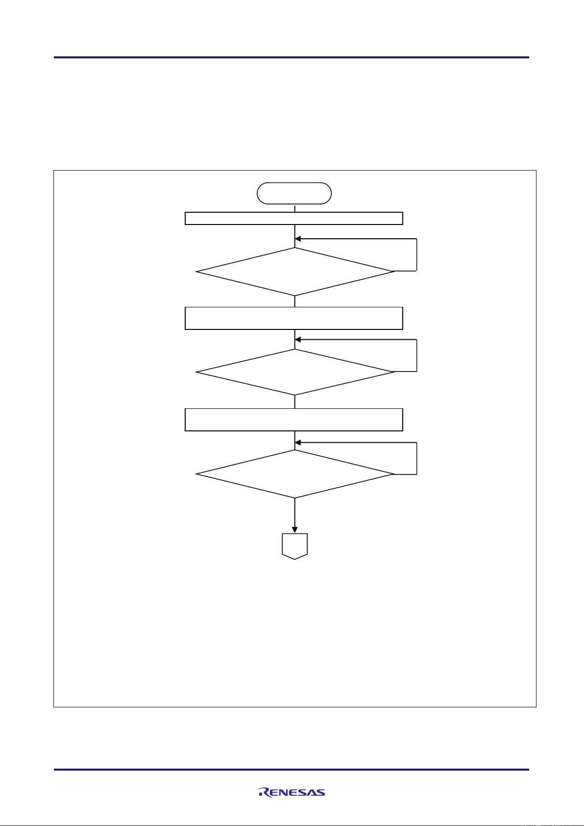
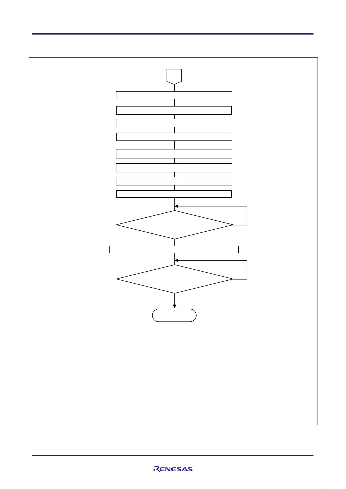
This document describes an example of a procedure for setting CAN Configuration using the RH850 series. Please
refer to the notes in the latest user's manual hardware edition for the settings of each register.
Operation Confirmed Devices
This document applies to the RH850 series.
The variables described in the text are as follows.
Table 1-1 Target Devices and Variables
Variable
Target MCU
RH850/E2x
RH850/E1M-S2
RH850/P1M-E
RS-CAN FD channel number
m
0~4
0~3
0~2
GAFLIDj, GAFLMj, GAFLP0j,
GAFLP1j Register numbers
j
0~15
0~15
0~15
Transmit/Receive FIFO buffer
number
k
0~14
0~11
0~8
Receive FIFO buffer number
x
0~7
0~7
0~7
Receive buffer number
q
0~79
0~63
0~47
Transmit buffer number
p
0~79
0~63
0~47
RAM test number
r
0~63
0~63
0~63
GAFLCFGi、GTINTSTSi
register number
i
0
0
0
Number of each status register
y
0~2
0,1
0,1
The functions marked with "★" in the text are applicable to cases where 2 or more channels are installed.
In the text, CFD is omitted from the register names.
R01AN6027EJ0100
Rev.1.0
RH850 Series CAN Configuration (CAN FD Mode)
R01AN6027EJ0100 Rev.1.0 Page
2
of 66
May 10, 2018
Contents
1. CAN Configuration ........................................................................................................... 3
2. CAN State (Mode) Transition .......................................................................................... 10
3. Communication Speed ................................................................................................... 19
4. Global Function .............................................................................................................. 23
5. Receive Rule Table ........................................................................................................ 30
6. Buffer, FIFO Buffer ......................................................................................................... 39
7. Global Error Interrupt ...................................................................................................... 50
8. Channel Function ........................................................................................................... 52
9. CAN-related Interrupt ..................................................................................................... 60
10. Transmitter Delay Compensation (Only in CAN FD Mode) ................................................... 62
11. Precautions for Processing Flow .................................................................................... 63
12. Appendix ........................................................................................................................ 65
RH850 Series CAN Configuration (CAN FD Mode)
R01AN6027EJ0100 Rev.1.0 Page
3
of 66
May 10, 2018
1. CAN Configuration
In CAN configuration, set the functions required for CAN communication. Perform the configuration when resets
MC, detects BUS failures, starts and restarts CAN communication after WAKEUP.
The stats available when performing CAN configuration are shown below. For CAN State (Mode), refer to “Section
2, CAN State (Mode) Transition”.
• After CAN module enable (the CAN0EN bit in the PER2 register is ''1'')
• Global reset mode
• Channel reset mode
• Channel halt mode
The required functions when setting CAN configuration are shown below. For details of each process, refer to the
following chapters.
• CAN state (mode) transition
• Communication speed
• Global function
• Receive rule table
• Buffer
• Global error interrupt
• Channel function
RH850 Series CAN Configuration (CAN FD Mode)
R01AN6027EJ0100 Rev.1.0 Page
4
of 66
May 10, 2018
1.1 CAN Configuration after CAN Module Enable
1.1.1 CAN Configuration after CAN Module Enable
Perform the initialization of entire RS-CANFD modules after resetting MCU.
1.1.2 Setting Procedures of CAN Configuration after CAN Module Enable
Figure 1-1 and Figure 1-2 shows the procedure of CAN Configuration after CAN Module Enable
【Note】
1.
After resetting the MCU, do not access to CAN for RAM before initializing the CAN RAM.
(the CAN0EN bit of the PER2 register is ''1'')
2.
If you change the global mode (the GSLPR bit of the GCTR register, GMDC [1: 0] bit), check that
the mode is switched in the GSTS register. Do not change the GMDC[1:0] bit until the mode is
switched.
3.
Rewrite the interface selection bit (RCMC bit) of GRMCFG register in global test mode only.
4.
If you change the channel mode (the GSLPR bit of the CmCTR register, GHMDC [1: 0] bit), check
that the mode is switched in the CmSTS register. Do not change the GHMDC[1:0] bit until the
mode is switched.
Figure 1-1 Procedure of CAN Configuration after resetting MCU 1/2
START
Transition from Global Stop Mode
to Global Reset Mode
*2
Initialized
CAN RAM?
*1
No
Yes
No
Yes
Transitioned
to Global Reset Mode?
*2
Transition from Channel Stop Mode
to Channel Reset Mode
*4
No
Transitioned
to Channel Reset Mode?
*4
Yes
CAN port setting
A
RH850 Series CAN Configuration (CAN FD Mode)
R01AN6027EJ0100 Rev.1.0 Page
5
of 66
May 10, 2018
【Note】
1.
For processes of each functions, refer to the following chapters.
2.
If you change the global mode (the GSLPR bit of the GCTR register, GMDC [1: 0] bit), check that
the mode is switched in the GSTS register. Do not change the GMDC[1:0] bit until the mode is
switched.
3.
If you change the channel mode (the GSLPR bit of the CmCTR register, GHMDC [1: 0] bit), check
that the mode is switched in the CmSTS register. Do not change the GHMDC[1:0] bit until the
mode is switched.
4.
After a transitions to channel communication mode, when 11 consecutive recessive bits have been
detected, communication is ready (the COMSTS flag in the CmSTS register is “1”) and
transmission and reception are enabled on the CAN network as an active node. At this time,
transmission and reception of messages can be started.
Figure 1-2 Procedure of CAN Configuration after resetting MCU 2/2
Global error interrupt setting
*1
Channel function setting
*1
CAN-related interrupt setting
*1
Receive rule setting
*1
Buffer setting
*1
Global function setting
*1
Communication speed setting
*1
END
Transition to channel communication mode
*3
No
Yes
Transitioned
to global operation mode?
*2
No
Yes
Transitioned to channel
communication mode?*
3, 4
Transition to global function mode
*2
A
剩余68页未读,继续阅读
不吃鱼的猫丿
- 粉丝: 638
- 资源: 8
上传资源 快速赚钱
- 我的内容管理 收起
- 我的资源 快来上传第一个资源
- 我的收益 登录查看自己的收益
- 我的积分 登录查看自己的积分
- 我的C币 登录后查看C币余额
- 我的收藏
- 我的下载
- 下载帮助
会员权益专享
最新资源
- BSC绩效考核指标汇总 (2).docx
- BSC资料.pdf
- BSC绩效考核指标汇总 (3).pdf
- C5000W常见问题解决方案.docx
- BSC概念 (2).pdf
- ESP8266智能家居.docx
- ESP8266智能家居.pdf
- BSC概念 HR猫猫.docx
- C5000W常见问题解决方案.pdf
- BSC模板:关键绩效指标示例(财务、客户、内部运营、学习成长四个方面).docx
- BSC概念.docx
- BSC模板:关键绩效指标示例(财务、客户、内部运营、学习成长四个方面).pdf
- BSC概念.pdf
- 各种智能算法的总结汇总.docx
- BSC概念 HR猫猫.pdf
- bsc概念hr猫猫.pdf
资源上传下载、课程学习等过程中有任何疑问或建议,欢迎提出宝贵意见哦~我们会及时处理!
点击此处反馈
安全验证
文档复制为VIP权益,开通VIP直接复制
信息提交成功