

swru208b
8/33
5.2 Running the Preprogrammed PER Test on the CC2530EM
The CC2530EM comes pre-programmed with a Packet Error Rate (PER) test application. The PER
number is the ratio between number of packets being lost and the total number of packets being sent.
The PER relates to the more traditional Bit Error Rate (BER) through the formula
lengthpacket
BERPER
_
)1(1
A PER value of 1% (when the packet length is 20 bytes) is normally used as the limit for determining
the sensitivity threshold of the radio. The sensitivity threshold is the lowest input signal strength at
which the receiver can decode the signal with a reasonable degree of correctness.
By using the PER test on the CC2530, it is possible to perform practical range testing. Place the
transmitter at a fixed location and place the receiver at a given distance from the transmitter. Then run
the PER test to measure packet errors and monitor the signal strength. Read the description below for
an explanation how the PER and RSSI values are calculated. Repeat at different distances to get an
idea of the range that can be obtained.
To get an idea of the best performance of the device, the test should be performed outdoors on a
large field with no other RF sources to avoid fading, reflections, and uncontrolled interference.
Alternatively, the range test can be used to see what range is obtainable in the actual environment
where the RF system is going to be deployed. See document [15] for considerations and applicable
theory for performing open field range measurements.
The CC2530DK Quick Start Guide (www.ti.com/lit/swra273) gives a detailed step-by-step guide for
running the PER test. We recommend following the steps in that guide.
Please note the following:
The most natural power source to use for range testing is batteries. There is a voltage
regulator on the SmartRF05EB that regulates the voltage to 3.3V on the board, regardless of
the voltage from the batteries. If the low batteries LED (LED D7 below the LCD) on the EB
board is turned on, the batteries should be changed.
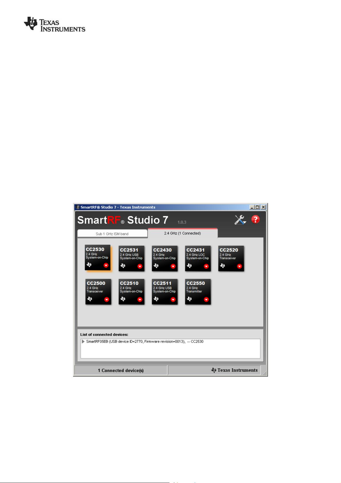
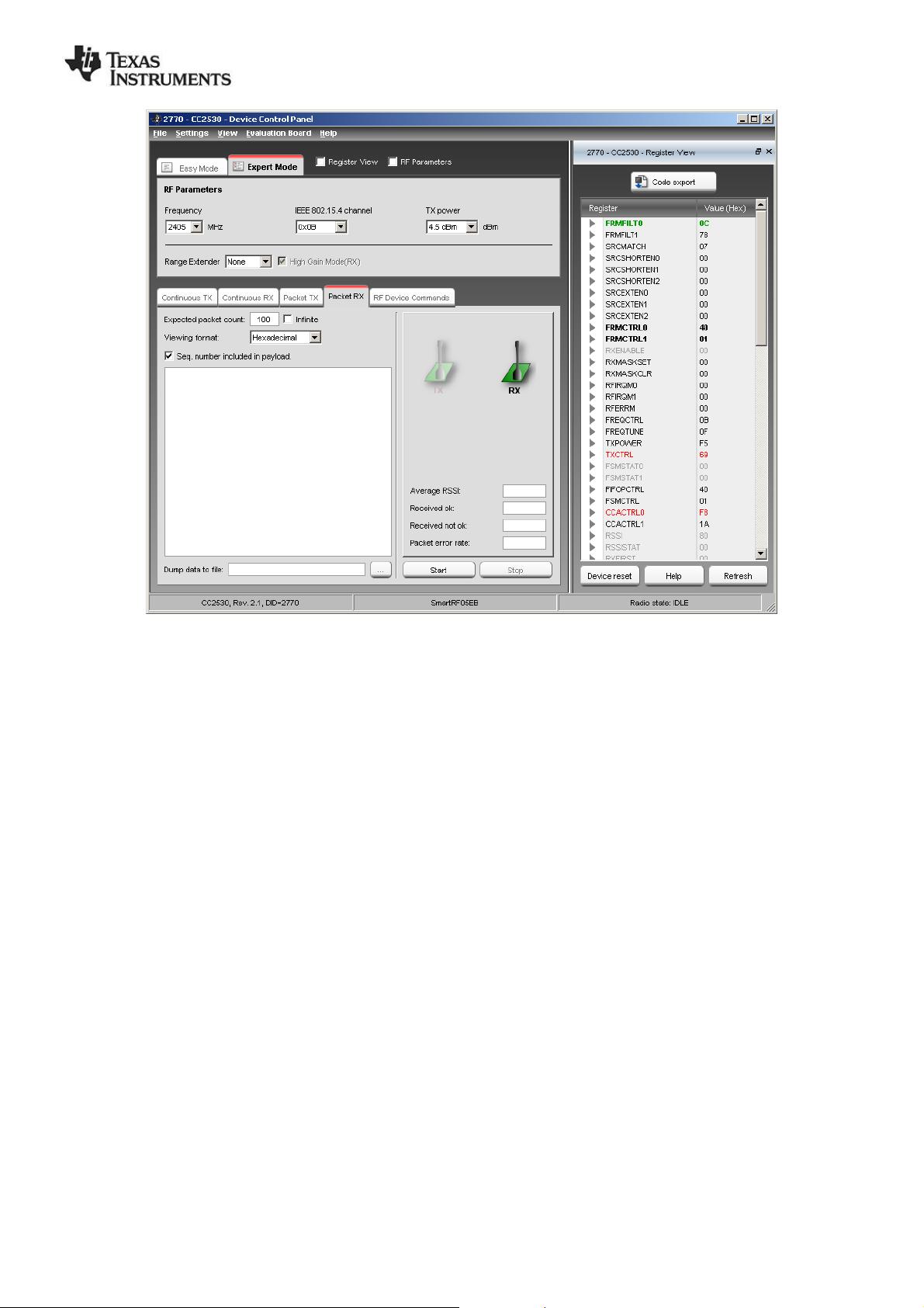
Both boards have to be set up to operate on the same channel. The channel is one of the 16
IEEE802.15.4 channels. The first channel (channel number 11, per the IEEE specification) is
at 2405 MHz, followed by channels in steps of 5 MHz up to 2480 MHz.
For the best range, use the highest possible output power on the transmitter.
The PER value is calculated using the following formula:
Errors
NumPackets
Lost
NumPackets
OK
NumPackets
ErrorsNumPacketsLostNumPackets
PER
The software is looking at the sequence number of the received packet to determine how
many packets are lost since the last received packet. The PER value on the LCD shows the
number per 1000 to avoid time consuming floating point calculations on the controller. That is,
if the LCD shows a PER of 6 / 1000, the PER value is 0.6%.
The RSSI value shown on the LCD is in dBm and represents the average RSSI value from the
last 32 received packets. The RSSI value will never be the same for all packets even though
the boards are located at the same distance from each other. This is caused by interfering
signals, reflections, thermal noise etc.
The source code for the PER test, and a Intel HEX file ready to be programmed on the device, is
included in the CC2530 Software Examples, available on the CC2530DK web site [3].
剩余45页未读,继续阅读

YL-Peach
- 粉丝: 1
- 资源: 3
 我的内容管理
展开
我的内容管理
展开


最新资源
- 计算机人脸表情动画技术发展综述
- 关系数据库的关键字搜索技术综述:模型、架构与未来趋势
- 迭代自适应逆滤波在语音情感识别中的应用
- 概念知识树在旅游领域智能分析中的应用
- 构建is-a层次与OWL本体集成:理论与算法
- 基于语义元的相似度计算方法研究:改进与有效性验证
- 网格梯度多密度聚类算法:去噪与高效聚类
- 网格服务工作流动态调度算法PGSWA研究
- 突发事件连锁反应网络模型与应急预警分析
- BA网络上的病毒营销与网站推广仿真研究
- 离散HSMM故障预测模型:有效提升系统状态预测
- 煤矿安全评价:信息融合与可拓理论的应用
- 多维度Petri网工作流模型MD_WFN:统一建模与应用研究
- 面向过程追踪的知识安全描述方法
- 基于收益的软件过程资源调度优化策略
- 多核环境下基于数据流Java的Web服务器优化实现提升性能
资源上传下载、课程学习等过程中有任何疑问或建议,欢迎提出宝贵意见哦~我们会及时处理!
点击此处反馈


