
2.Modeling Casting Process
Simulation Types
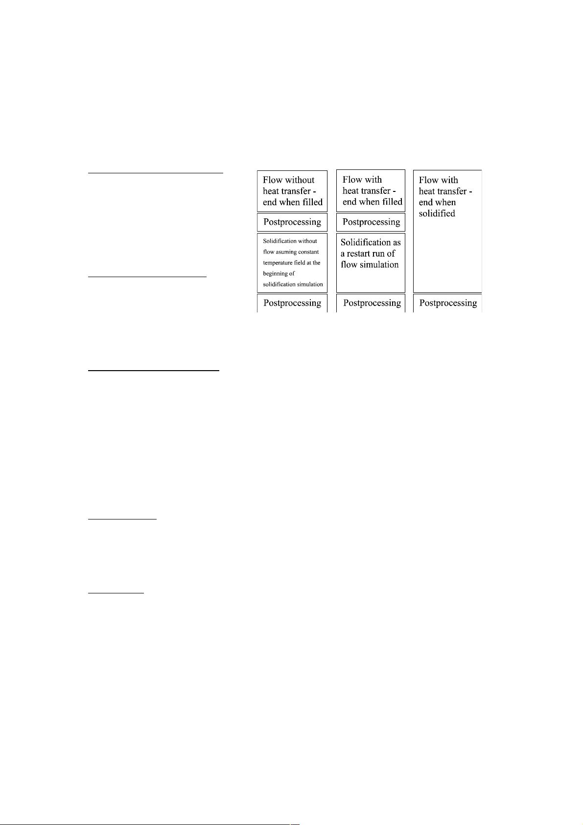
Flow without heat transfer
Many filling problems are not heat
transfer related. Such problems are best
simulated as simple flow problems
without heat transfer enabled. This will
make the simulation run faster. The
calculation end criteria should be ‘part
filled’.
Flow with heat transfer
Heat transfer can be simulated during
the filling. Typically the end criteria
should be ‘end when part filled’ and the
solidification is then simulated
separately as a restart run. It is possible
- though not recommended - to simulate both as a single simulation
Solidification without flow
Usually solidification is simulated separately from the filling. It can be run as a restart run (see later) that
utilizes the data from filling simulation as a starting point or as a completely separate simulation from
the filling.
When simulating solidification as a completely separate simulation from we assume that at the
beginning of simulation the mould is fully filled and that the metal and the mould have uniform
temperature field. In reality heat transfer happens already during the filling and the temperature fields
are not uniform but in many cases the impact of the heat transfer during the filling is not significant.
Simulation Project Files
Restart Runs
Restart runs is a technique which allows to have a simulation which continues from the end situation of
another simulation. Typical application of this technique is to run solidification simulation separately as
a restart run of filling simulation. Metal concentration and then temperature values are loaded from the
filling simulation, but calculation modes and meshing can be changed.
Versioning
It is often useful to run several variants of the simulation. Initially it is a good idea to first run a
simulation with a very coarse mesh to make sure that the geometry, border conditions, temperatures
etc settings are correct. This way you get the first feedback quickly. Then once the simulation setup is
correct then run the simulation with more accurate mesh. Then, after first results, if there are problems
make improvements to the casting system and then simulate again.
FLOW-3D® Cast supports having several versions of a simulation. Simulation version is identified by
a version number and further information about the version can be added to simulation description.
Both of these can be modified in Casting Properties dialog.
When you create a restart run the version number is reset. The restart runs have their own version
number independently of the original simulation from where they fetch the initial data values for
temperature, metal concentration etc. Thus, you can have several different restart simulation versions
all continuing from the same original simulation.
User Manual: FLOW-3D
®
Cast 3.2
Figure 2 Simulation types
9

剩余48页未读,继续阅读

bruceuwa
- 粉丝: 0
- 资源: 2
 我的内容管理
展开
我的内容管理
展开


最新资源
- OptiX传输试题与SDH基础知识
- C++Builder函数详解与应用
- Linux shell (bash) 文件与字符串比较运算符详解
- Adam Gawne-Cain解读英文版WKT格式与常见投影标准
- dos命令详解:基础操作与网络测试必备
- Windows 蓝屏代码解析与处理指南
- PSoC CY8C24533在电动自行车控制器设计中的应用
- PHP整合FCKeditor网页编辑器教程
- Java Swing计算器源码示例:初学者入门教程
- Eclipse平台上的可视化开发:使用VEP与SWT
- 软件工程CASE工具实践指南
- AIX LVM详解:网络存储架构与管理
- 递归算法解析:文件系统、XML与树图
- 使用Struts2与MySQL构建Web登录验证教程
- PHP5 CLI模式:用PHP编写Shell脚本教程
- MyBatis与Spring完美整合:1.0.0-RC3详解
资源上传下载、课程学习等过程中有任何疑问或建议,欢迎提出宝贵意见哦~我们会及时处理!
点击此处反馈


