双星永磁同步发电机的通用解耦d-q模型分析
需积分: 9 186 浏览量
更新于2024-09-12
收藏 635KB PDF 举报
"分析双星永磁同步发电机的通用解耦d-q模型"
在电力系统和可再生能源领域,双星永磁同步发电机(Double-Star Permanent-Magnet Synchronous Generators,DSPMSG)因其高效率和紧凑的设计而备受关注。本文“DECOUPLING METHOD”着重探讨了一种用于分析这类发电机的通用解耦d-q模型的方法。d-q坐标系是电机分析中的重要工具,它能将复杂的三相系统简化为两个相互独立的单相系统。
作者Mauro Andriollo、Giulio Bettanini、Giovanni Martinelli、Augusto Morini和Andrea Tortella在2009年的IEEE Transactions on Industry Applications期刊上发表的这篇论文指出,传统的分析方法往往忽视了双星结构中两组三相绕组之间的相互作用以及无负载时磁链的谐波成分。他们提出的新技术通过将两组三相绕组转换为转子参考框架下的两对d-q轴绕组,解决了这个问题。
该解耦方法的一个显著优势在于,它考虑了两组绕组之间的任意角度偏移,并且能够处理无负载磁链的谐波效应。这不仅提高了分析的准确性,还大大简化了分析过程,因为转换后的两组绕组在数学上是互相独立的,从而降低了计算复杂性。
文章第一部分(I. INTRODUCTION)强调了分布式发电和可再生能源利用背景下的电机建模的重要性。双星永磁同步发电机在这一背景下扮演着关键角色,因为它们能够有效地将各种能源转化为电能,包括风能、太阳能以及工业和农业副产品。
通过引入这种解耦技术,工程师和研究人员可以更深入地理解双星永磁同步发电机的动态性能和电磁特性,这对于优化设计、控制策略的开发以及故障诊断具有重要意义。此外,这种方法还可以为其他类型的多相电机提供参考,推动电机技术的发展。
总结来说,该研究提出的解耦d-q模型为分析双星永磁同步发电机提供了一个强大且灵活的工具,它能够处理复杂的电磁现象,提高分析精度,同时简化了分析流程,对于电机设计和控制领域的实践应用具有深远的影响。
1416 IEEE TRANSACTIONS ON INDUSTRY APPLICATIONS, VOL. 45, NO. 4, JULY/AUGUST 2009
Analysis of Double-Star Permanent-Magnet
Synchronous Generators by a General
Decoupled
d–q Model
Mauro Andriollo, Giulio Bettanini, Giovanni Martinelli, Augusto Morini, and Andrea Tortella
Abstract—This paper proposes a technique to analyze double-
star permanent-magnet synchronous generators by transforming
the two three-phase winding sets into two couples of windings on
the d-andq-axes of the rotor reference frame. The technique
introduces improvements with respect to other approaches, as
it takes into account the harmonic content of the no-load flux
linkages of the armature windings, it applies to a generic angular
displacement between the two winding sets, and it greatly sim-
plifies the analysis since the two transformed winding sets are
decoupled with respect to each other.
Index Terms—Electric machine modeling, permanent-magnet
(PM) machines, windings.
I. INTRODUCTION
I
N THE frame of the growing utilization of distributed
generation and, in particular, of the renewable sources and
of the industrial and agricultural by-products and wastes, low-
and medium-rating permanent-magnet synchronous generators
(PMSGs) meet with increasing application. Although the three-
phase winding configurations are dominant, nevertheless, the
double-star windings offer several benefits in terms of lower dc-
link current/voltage ripple, lower torque pulsation (particularly
critical in systems driven by high speed microturbines), and
higher reliability. Furthermore, the series–parallel connection
of the rectified outputs of two distinct three-phase groups may
represent a favorable option for a variable-speed wind-turbine-
driven generation system.
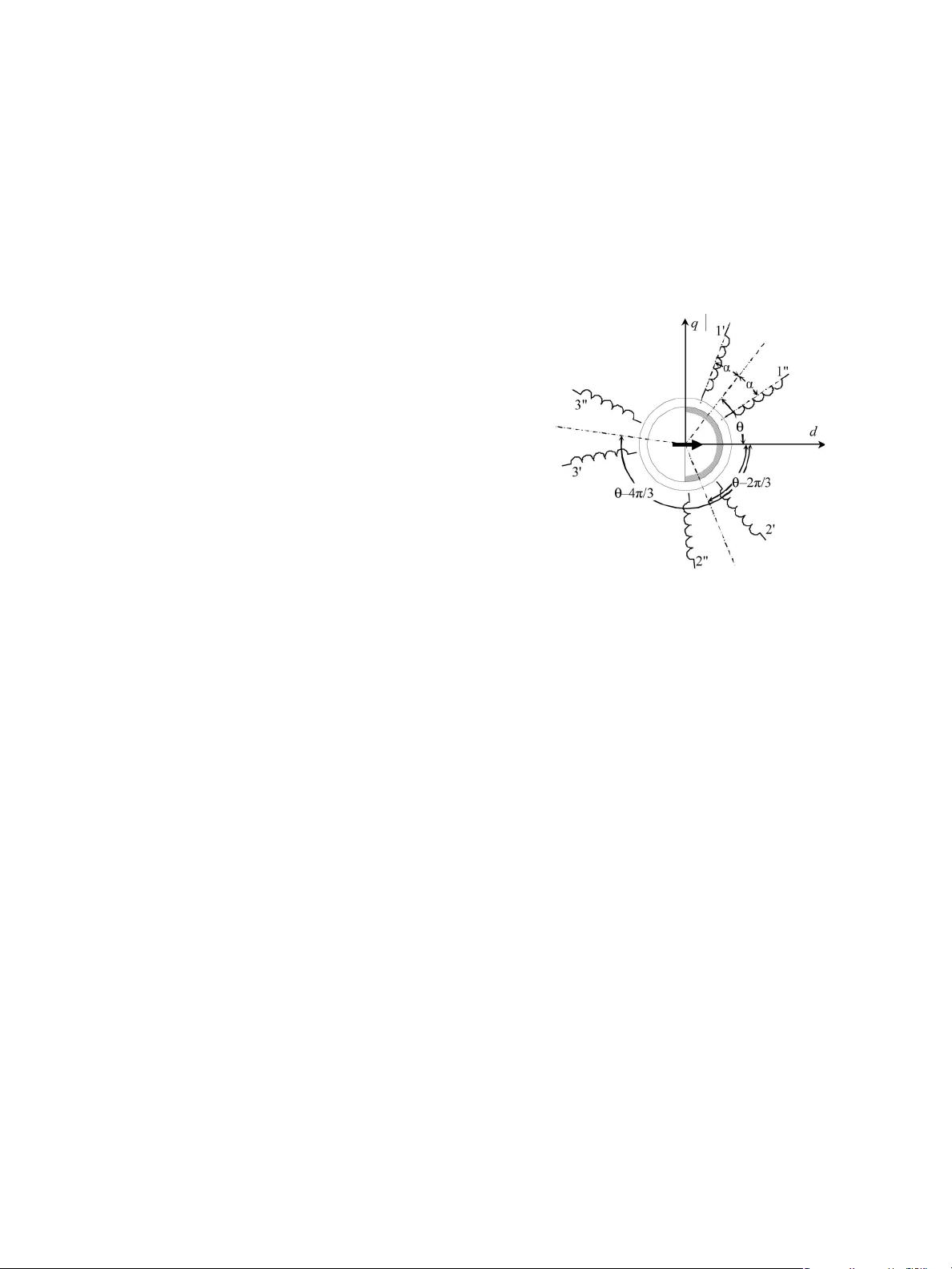
The proposed technique analyzes the double-star PMSG by
transforming the stator three-phase winding sets {1
, 2
, 3
}
and {1
, 2
, 3
} (Fig. 1) into two couples of windings on the
d- and q-axes of the rotor reference frame. With respect to
other approaches [1]–[4], the methodology offers the following
improvements.
1) It takes into account the harmonic content of the no-load
flux linkages of the armature windings.
2) It applies to a generic angular displacement 2α between
the two winding sets.
Paper 2008-EMC-042.R1, presented at the 2007 IEEE International Electric
Machines and Drives Conference, Antalya, Turkey, May 3–5, and approved
for publication in the IEEE T
RANSACTIONS ON INDUSTRY APPLICATIONS
by the Electric Machines Committee of the IEEE Industry Applications Society.
Manuscript submitted for review July 23, 2008 and released for publication
February 19, 2009. First published June 2, 2009; current version published
July 17, 2009.
The authors are with the Department of Electrical Engineering, University
of Padova, 35131 Padova, Italy (e-mail: mauro.andriollo@unipd.it; giulio.
bettanini@unipd.it; giovanni.martinelli@unipd.it; augusto.morini@unipd.it;
andrea.tortella@unipd.it).
Digital Object Identifier 10.1109/TIA.2009.2023553
Fig. 1. Winding arrangement and definition of angular quantities (θ: rotor
position expressed by the angle between the d-axis and the 1
− 1
phase axes
bisector).
3) It greatly simplifies the analysis since the two trans-
formed winding sets are decoupled with respect to each
other.
II. D
ESCRIPTION OF THE METHOD
In the hypotheses of equal symmetrical three-phase wind-
ings, rotor isotropic magnetic structure, and negligible satu-
ration effects, the following equalities hold for the armature
inductances:
L
1
1
= L
2
2
= L
3
3
= L
1
1
= L
2
2
= L
3
3
= L
s
M
1
2
= M
2
3
= M
3
1
= M
1
2
= M
2
3
= M
3
1
= M
s
M
1
1
= M
2
2
= M
3
3
= M
a
M
1
2
= M
2
3
= M
3
1
= M
b
M
1
3
= M
2
1
= M
3
2
= M
c
. (1)
Let δ = θ ± α be the angular displacement of the axis of the
reference stator winding (1
or 1
) with respect to the d-axis,
and let λ
fs
(δ) be its no-load flux linkage due to the permanent
magnets (PMs). To evaluate the winding voltages, the PMs
can be replaced by an equivalent rotor winding supplied by a
constant current I
f
, where M
fs
(δ)=λ
fs
(δ)/I
f
is the mutual
inductance with the stator winding, and L
f
(θ)=λ
f
(θ)/I
f
is
0093-9994/$25.00 © 2009 IEEE
下载后可阅读完整内容,剩余8页未读,立即下载
点击了解资源详情
1341 浏览量
105 浏览量
114 浏览量
144 浏览量
2025-03-13 上传

Y-Guii
- 粉丝: 0
 我的内容管理
展开
我的内容管理
展开


最新资源
- Linux平台PSO服务器管理工具集:简化安装与维护
- Swift仿百度加载动画组件BaiduLoading
- 传智播客C#十三季完整教程下载揭秘
- 深入解析Inter汇编架构及其基本原理
- PHP实现QQ群聊天发言数统计工具 v1.0
- 实用AVR驱动集:IIC、红外与无线模块
- 基于ASP.NET C#的学生学籍管理系统设计与开发
- BEdita Manager:官方BEdita4 API网络后台管理应用入门指南
- 一天掌握MySQL学习笔记及实操练习
- Sybase数据库安装全程图解教程
- Service与Activity通信机制及MyBinder类实现
- Vue级联选择器数据源:全国省市区json文件
- Swift实现自定义Reveal动画播放器效果
- 仿53KF在线客服系统源码发布-多用户版及SQL版
- 利用Android手机实现远程监视系统
- Vue集成UEditor实现双向数据绑定
