

Design Considerations for Electrical
Fast Transient (EFT) Immunity
www.cypress.com Document No. 001-80994 Rev. *H 9
4 Performance Criteria
The loss of functionality or degradation of performance of a controller, relative to the performance as defined by its
specifications, per IEC 61000-4-4, can be categorized into the following criteria
Table 2. Performance Criteria
Criteria
Description
Performance Criteria A
Normal performance after the test is within limits as specified by the manufacturer.
Performance Criteria B
Temporary loss of function or degradation of the performance during the test; the controller
recovers to its normal performance without any intervention after the test.
Performance Criteria C
Temporary loss of function or degradation of the performance during the test; the controller
recovers to its normal performance with intervention after the test.
Performance Criteria D
Loss of function or degradation of the performance during the test; the controller does not recover
owing to damage.
It is important to note that a condition assessed as failure for a particular system may not be a failure with respect to
another system. For example, an industrial process controller cannot tolerate intermittent device resets during EFT
testing but a user interface may. Therefore, give due consideration to the end-application requirements and its ability
to tolerate transient noise.
5 Troubleshooting and Methods to Improve EFT Immunity of a Failing
System
Effective troubleshooting of problems due to transient-induced noise is nontrivial even though it is often overlooked as
part of system compliance testing and bring-up. Designers should ascertain the probable causes for each failure
observed as part of compliance testing. The designer and the person responsible for running compliance tests must
work together to isolate the causes for the failures.
Most failures that occur in systems employing microcontrollers can be quickly identified if due cognizance is paid to
the type of failure. You should identify the failure modes discussed in the previous section occurring in a system
during or after EFT tests and their causes.
Once you understand the probable causes for the associated failures, take a step-by-step approach to debug the
cause. Some tips for troubleshooting are:
1. When looking for a reset-related issue, probe the supply pins of the controller during the test and look for obvious
reasons. Place a debug routine in the firmware that can visually indicate a reset.
2. In the case of a latch-up, observe whether the current drawn by the controller is beyond its normal ratings. If that
is not the case, look for a firmware freeze by introducing debug routines.
3. For analog or clock-related issues, probe the associated I/O lines for noise or glitches. Pay attention to clock
stretches if the communications to the device are hampered.
4. For flash/RAM corruptions, place a firmware debug routine such as a port pin toggling and monitor the pin status
to check if the firmware flow is as intended. Read susceptible memory contents during and after the tests.
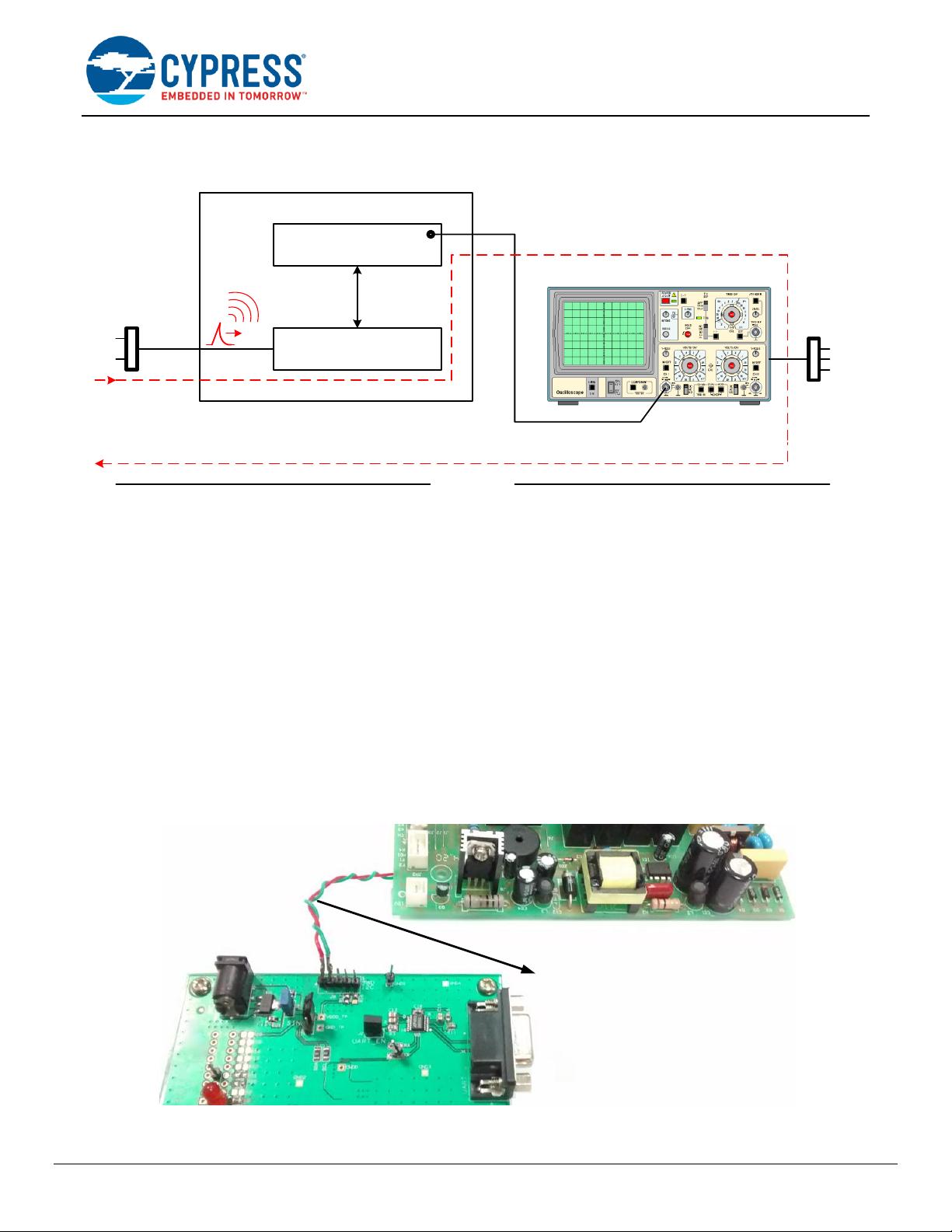
Note that it is advised to use oscilloscopes with isolated earth grounds. Failing to do so might cause the oscilloscope
earth ground to shunt transient noise thus giving wrong readings. In a typical oscilloscope, the signal ground is
connected to the earth ground internally. Refer to Figure 7.
剩余47页未读,继续阅读

komonder
- 粉丝: 12
- 资源: 20
 我的内容管理
展开
我的内容管理
展开


最新资源
- 计算机人脸表情动画技术发展综述
- 关系数据库的关键字搜索技术综述:模型、架构与未来趋势
- 迭代自适应逆滤波在语音情感识别中的应用
- 概念知识树在旅游领域智能分析中的应用
- 构建is-a层次与OWL本体集成:理论与算法
- 基于语义元的相似度计算方法研究:改进与有效性验证
- 网格梯度多密度聚类算法:去噪与高效聚类
- 网格服务工作流动态调度算法PGSWA研究
- 突发事件连锁反应网络模型与应急预警分析
- BA网络上的病毒营销与网站推广仿真研究
- 离散HSMM故障预测模型:有效提升系统状态预测
- 煤矿安全评价:信息融合与可拓理论的应用
- 多维度Petri网工作流模型MD_WFN:统一建模与应用研究
- 面向过程追踪的知识安全描述方法
- 基于收益的软件过程资源调度优化策略
- 多核环境下基于数据流Java的Web服务器优化实现提升性能
资源上传下载、课程学习等过程中有任何疑问或建议,欢迎提出宝贵意见哦~我们会及时处理!
点击此处反馈


