
IR35204
www.irf.com | © 2016 International Rectifier February 8, 2016 | V1.6
11
3+1 Dual Output Digital Multi-Phase Controller
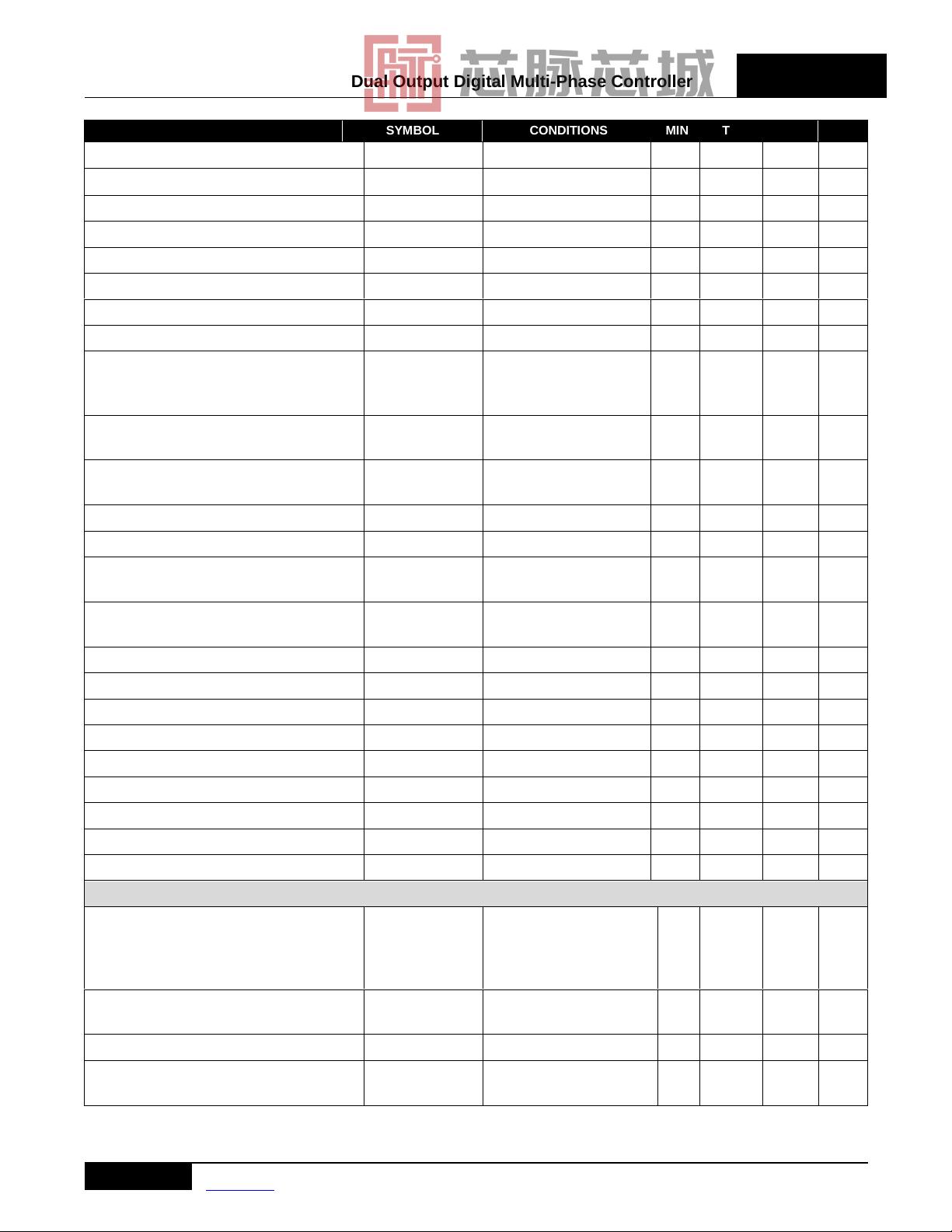
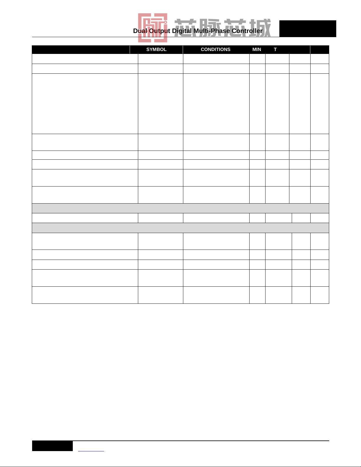
PARAMETER SYMBOL CONDITIONS MIN TYP MAX UNIT
Vin Accuracy Reporting With 1% resistors -2 - +2 %
Vin Resolution Reporting -PMBUS
1
- 31.25 - mV
Vin Resolution Reporting –I2C
1
- 125 - mV
Vout Range Reporting
1
- - 4 V
Vout Accuracy Reporting
1
No load-line ±0.5 %
Vout Resolution Reporting-PMBUS
1
Vout < 2V - 1.95 - mV
Vout Resolution Reporting-I2C
1
Vout < 4V - 15.6 - mV
Iout Per Phase Range Reporting
1
0 - 62 A
Iout Accuracy Reporting
1
Maximum load, all phase
active (based on DCR,
NTC and # active phases)
- ±2 - %
Loop1 Iout Resolution Reporting-
PMBUS
1
*0.5A if >255.75A - 0.25* - A
Loop2 Iout Resolution Reporting-
PMBUS
1
- 0.25 - A
Loop1 Iout Resolution Reporting-I2C
1
- 1 - A
Loop2 Iout Resolution Reporting-I2C
1
- 0.5 - A
Loop1 Iin Resolution Reporting-PMBUS
1
- 31.25 - mA
Loop2 Iin Resolution Reporting-PMBUS
1
- 31.25 - mA
Loop1 Iin Resolution Reporting-I2C
1
- 0.125 - A
Loop2 Iin Resolution Reporting-I2C
1
- 0.0625 - A
P_in Resolution Reporting-PMBUS
1
- 0.5 - W
P_out Resolution Reporting-PMBUS
1
- 0.5 - W
Temperature Range Reporting1 IR3555 mode 0 - 158 °C
Temperature Accuracy Reporting1 IR3555 mode 3.5 - 3.5 %
Temperature Range Reporting
1
0 - 134 °C
Temperature Accuracy Reporting
1
At 100°C, with ideal NTC -4 - 4 %
Temperature Resolution Reporting
1
- 1 - °C
Fault Protection
OVP Threshold During Start-up
(until output reaches 1V)
Selectable -
1.2,
1.275,
1.35,
2.5
- V
OVP Operating Threshold
1
(programmable)
Relative to VID -
50 to
400
- mV
OVP Filter Delay
1
- 160 - ns
Output UVP Threshold
1
(programmable)
Relative to VID -
50 to
400
- mV

剩余60页未读,继续阅读

芯脉芯城
- 粉丝: 3
- 资源: 4030
 我的内容管理
收起
我的内容管理
收起
- 我的资源
快来上传第一个资源
 我的收益 登录查看自己的收益
 我的积分
登录查看自己的积分
我的积分
登录查看自己的积分
 我的C币
登录后查看C币余额
我的C币
登录后查看C币余额
 我的收藏
我的收藏  我的下载
我的下载  下载帮助
下载帮助

会员权益专享


最新资源
- 谷歌文件系统下的实用网络编码技术在分布式存储中的应用
- 跨国媒体对南亚农村社会的影响:以斯里兰卡案例的社会学分析
- RFM2g接口驱动操作手册:API与命令行指南
- 基于裸手的大数据自然人机交互关键算法研究
- ABAQUS下无人机机翼有限元分析与局部设计研究
- TCL基础教程:语法、变量与操作详解
- FPGA与数字前端面试题集锦:流程、设计与Verilog应用
- 2022全球互联网技术人才前瞻:元宇宙驱动下的创新与挑战
- 碳排放权交易实战手册(第二版):设计与实施指南
- 2022新经济新职业洞察:科技驱动下的百景变革
- 红外与可见光人脸融合识别技术探究
- NXP88W8977:2.4/5 GHz 双频 Wi-Fi4 + Bluetooth 5.2 合体芯片
- NXP88W8987:集成2.4/5GHz Wi-Fi 5与蓝牙5.2的单芯片解决方案
- TPA3116D2DADR: 单声道数字放大器驱动高达50W功率
- TPA3255-Q1:315W车载A/D类音频放大器,高保真、宽频设计
- 42V 输入 5A 降压稳压器 TPS54540B-Q1 的特点和应用
资源上传下载、课程学习等过程中有任何疑问或建议,欢迎提出宝贵意见哦~我们会及时处理!
点击此处反馈


