没有合适的资源?快使用搜索试试~ 我知道了~
首页SD卡协会发布SD协议2.0原版规范
SD卡协会发布SD协议2.0原版规范
需积分: 50 6 下载量 190 浏览量
更新于2024-07-26
收藏 1.04MB PDF 举报
"SD协议2.0原版.pdf" SD协议2.0是SD卡协会(SD Card Association)发布的一份重要的技术规范,旨在规范SD卡的物理层设计和实现。该协议的发布对SD卡行业的发展产生了深远的影响。 SD协议2.0的主要内容包括物理层规范、SD卡的电气特性、时序特性、数据传输协议等方面。该协议还规定了SD卡的各种类型,包括SDHC、SDXC、SDUC等。 物理层规范是SD协议2.0的核心内容之一,该规范规定了SD卡的物理层设计,包括信号线路、时序特性、电气特性等方面。物理层规范的实施对SD卡的可靠性和兼容性产生了重要的影响。 SD协议2.0还规定了SD卡的数据传输协议,包括数据传输模式、数据传输速度、数据传输协议等方面。该协议还规定了SD卡的安全机制,包括数据加密、身份验证等方面。 SD协议2.0的发布对SD卡行业的发展产生了深远的影响,促进了SD卡技术的发展和应用。该协议的实施对SD卡的可靠性、兼容性和安全性产生了重要的影响。 在SD协议2.0的基础上, SD卡协会还发布了一些相关的技术规范,包括SDHC规范、SDXC规范、SDUC规范等。这些规范对SD卡的发展和应用产生了重要的影响。 SD协议2.0还规定了SD卡的测试和验证规范,包括SD卡的功能测试、性能测试、兼容性测试等方面。该协议还规定了SD卡的生产和检测规范,包括SD卡的生产流程、检测流程等方面。 SD协议2.0是SD卡行业的重要技术规范,对SD卡的发展和应用产生了深远的影响。该协议的实施对SD卡的可靠性、兼容性和安全性产生了重要的影响。 "SD协议2.0原版.pdf"
资源详情
资源推荐
©Copyright 2001-2006 SD Group (Panasonic, SanDisk, Toshiba) and SD Card Association
Physical Layer Simplified Specification Version 2.00
5
3. SD Memory Card System Concept
Description here is a blank for the Simplified Specification.
3.1 Read-Write Property
In terms of read-write property, two types of SD Memory Cards are defined:
• Read/Write (RW) cards (Flash, One Time Programmable - OTP, Multiple Time Programmable -
MTP). These cards are typically sold as blank (empty) media and are used for mass data storage,
end user video, audio or digital image recording
• Read Only Memory (ROM) cards. These cards are manufactured with fixed data content. They are
typically used as a distribution media for software, audio, video etc.
3.2 Supply Voltage
In terms of operating supply voltage, two types of SD Memory Cards are defined:
• High Voltage SD Memory Cards that can operate within the voltage range of 2.7-3.6 V.
• Dual Voltage SD Memory Cards –Dual Voltage SD Memory Cards that can operate within the
voltage range of Low Voltage Range (T.B.D) and 2.7-3.6 V.
Note that details of Dual Voltage SD Memory Card will be defined in future specification.
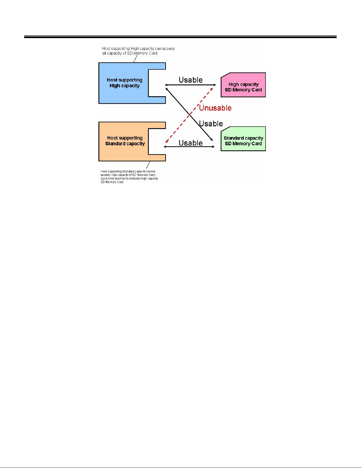
3.3 Card Capacity
In terms of capacity, two types of SD Memory Cards are defined:
• Standard Capacity SD Memory Cards supports capacity up to and including 2 G bytes (2
31
bytes).
All versions of the Physical Specifications define the Standard Capacity SD Memory Card.
• High Capacity SD Memory Cards supports capacity more than 2 G bytes (2
31
bytes) and this version
of specification limits capacity up to and including 32 GB. High Capacity SD Memory Card is newly
defined from the Physical Layer Specification Version 2.00.
Only hosts that are compliant to the Physical Layer Specification version 2.00 or higher and the SD File
System Specification Ver2.00 can access High Capacity SD Memory Cards. Other hosts fail to initialize
High Capacity SD Memory Cards (See Figure 3-1).
Note:
1. The Part 1 Physical Layer Specification Version 2.00 and Part 2 File System Specification
Version 2.00 allow Standard Capacity SD Memory Cards to have capacity up to and
including 2 GB and High Capacity SD Memory Cards to have capacity up to and including
32 GB. SD Memory Cards with a capacity greater than 32 GB will be available with updated
versions of Part 1 and Part 2 Specifications.
2. Hosts that can access (read and/or write) SD Memory Cards with a capacity greater than 2
GB and up to and including 32 GB, shall also be able to access SD Memory Cards with a
capacity of 2 GB or less.
©Copyright 2001-2006 SD Group (Panasonic, SanDisk, Toshiba) and SD Card Association
Physical Layer Simplified Specification Version 2.00
6
Figure 3-1: Hosts-Cards Usability
• 2 types of High Capacity SD Memory Card are specified. Type A (Single State Card) has single High
Capacity memory area. Details of Type A are specified in the Physical Layer Specification version
2.00. Type B (Dual State Card) has both High Capacity memory area and Standard Capacity
memory area. In Type B card, only one memory area can be used at any given time. A mechanical
switch is used to select the desired memory area. Details of Type B will be defined in future
specifications. It is not necessary for the host to distinguish card types.
3.4 Speed Class
Four Speed Classes are defined and indicate minimum performance of the cards
• Class 0 - These class cards do not specify performance. It includes all the legacy cards prior to
this specification, regardless of its performance
• Class 2 - Are more than or equal to 2 MB/sec performance.
• Class 4 - Are more than or equal to 4 MB/sec performance.
• Class 6 - Are more than or equal to 6 MB/sec performance.
High Capacity SD Memory Cards shall support Speed Class Specification and have performance more
than or equal to Class 2.
Note that the unit of performance [MB/sec] indicates 1000x1000 [Byte/sec] while the unit of data size
[MB] indicates 1024x1024 [Byte]. This is because the maximum SD Bus speed is specified by the
maximum SD clock frequency (25 [MB/sec] = 25000000 [Byte/sec] at 50 MHz) and data size is based
on memory boundary (power of 2).
©Copyright 2001-2006 SD Group (Panasonic, SanDisk, Toshiba) and SD Card Association
Physical Layer Simplified Specification Version 2.00
7
3.5 Bus Topology
This section is a blank for the Simplified Specification.
3.6 Bus Protocol
3.6.1 SD Bus
Communication over the SD bus is based on command and data bit streams that are initiated by a start
bit and terminated by a stop bit.
• Command: a command is a token that starts an operation. A command is sent from the host either
to a single card (addressed command) or to all connected cards (broadcast command). A command
is transferred serially on the CMD line.
• Response: a response is a token that is sent from an addressed card, or (synchronously) from all
connected cards, to the host as an answer to a previously received command. A response is
transferred serially on the CMD line.
• Data: data can be transferred from the card to the host or vice versa. Data is transferred via the
data lines.
Figure 3-2: “no response” and “no data” Operations
Card addressing is implemented using a session address, assigned to the card during the initialization
phase. The structure of commands, responses and data blocks is described in Chapter 4. The basic
transaction on the SD bus is the command/response transaction (refer to Figure 3-2). This type of bus
transaction transfers their information directly within the command or response structure. In addition,
some operations have a data token.
Data transfers to/from the SD Memory Card are done in blocks. Data blocks are always succeeded by
CRC bits. Single and multiple block operations are defined. Note that the Multiple Block operation mode
is better for faster write operation. A multiple block transmission is terminated when a stop command
follows on the CMD line. Data transfer can be configured by the host to use single or multiple data lines.
command response
command response
block read operation
data stop operation
CMD
DAT
from
host
to card
stop command
stops data transfer
data from card
to host
from
card
to host
data block crc
data block crc data block crc
multiple block read operation
Figure 3-3: (Multiple) Block Read Operation
The block write operation uses a simple busy signaling of the write operation duration on the DAT0 data
line (see Figure 3-4) regardless of the number of data lines used for transferring the data.
©Copyright 2001-2006 SD Group (Panasonic, SanDisk, Toshiba) and SD Card Association
Physical Layer Simplified Specification Version 2.00
8
Figure 3-4: (Multiple) Block Write Operation
Command tokens have the following coding scheme:
Figure 3-5: Command Token Format
Each command token is preceded by a start bit (0) and succeeded by an end bit (1). The total length is
48 bits. Each token is protected by CRC bits so that transmission errors can be detected and the
operation may be repeated.
Response tokens have one of four coding schemes, depending on their content. The token length is
either 48 or 136 bits. The detailed commands and response definition is given in Chapter 4.7. The CRC
protection algorithm for block data is a 16-bit CCITT polynomial. All allowed CRC types are described in
Chapter 4.5.
00
CONTENT
1
total length=48 bits
start bit:
always'0'
transmitter bit:
'0'=card response
end bit:
always '1'
Response content: mirrored command and status infor-
mation (R1 response), OCR register (R3 response) or
RCA (R6), protected by a 7bit CRC checksum
R1, R3,R6
0
0 CONTENT=CID or CSD
total length=136 bits
R2
1
end bit:
always '1'
CRC
Figure 3-6: Response Token Format
In the CMD line the Most Significant Bit (MSB) is transmitted first, the Least Significant Bit (LSB) is the
last.
When the wide bus option is used, the data is transferred 4 bits at a time (refer to Figure 3-8). Start and
end bits, as well as the CRC bits, are transmitted for every one of the DAT lines. CRC bits are
calculated and checked for every DAT line individually. The CRC status response and Busy indication
will be sent by the card to the host on DAT0 only (DAT1-DAT3 during that period are don’t care).
©Copyright 2001-2006 SD Group (Panasonic, SanDisk, Toshiba) and SD Card Association
Physical Layer Simplified Specification Version 2.00
9
There are two types of Data packet format for the SD card.
(1) Usual data (8-bit width): The usual data (8-bit width) are sent in LSB (Least Significant Byte) first,
MSB (Most Significant Byte) last sequence. But in the individual byte, it is MSB (Most Significant Bit)
first, LSB (Least Significant Bit) last.
(2) Wide width data (SD Memory Register): The wide width data is shifted from the MSB bit.
Figure 3-7: Data Packet Format - Usual Data
剩余128页未读,继续阅读
single104
- 粉丝: 9
- 资源: 7
上传资源 快速赚钱
- 我的内容管理 展开
- 我的资源 快来上传第一个资源
- 我的收益 登录查看自己的收益
- 我的积分 登录查看自己的积分
- 我的C币 登录后查看C币余额
- 我的收藏
- 我的下载
- 下载帮助
最新资源
- C++多态实现机制详解:虚函数与早期绑定
- Java多线程与异常处理详解
- 校园导游系统:无向图实现最短路径探索
- SQL2005彻底删除指南:避免重装失败
- GTD时间管理法:提升效率与组织生活的关键
- Python进制转换全攻略:从10进制到16进制
- 商丘物流业区位优势探究:发展战略与机遇
- C语言实训:简单计算器程序设计
- Oracle SQL命令大全:用户管理、权限操作与查询
- Struts2配置详解与示例
- C#编程规范与最佳实践
- C语言面试常见问题解析
- 超声波测距技术详解:电路与程序设计
- 反激开关电源设计:UC3844与TL431优化稳压
- Cisco路由器配置全攻略
- SQLServer 2005 CTE递归教程:创建员工层级结构
资源上传下载、课程学习等过程中有任何疑问或建议,欢迎提出宝贵意见哦~我们会及时处理!
点击此处反馈
安全验证
文档复制为VIP权益,开通VIP直接复制
信息提交成功