MTL5000系列隔离器:简化系统规划与安装
64 浏览量
更新于2024-07-14
收藏 2.58MB PDF 举报
"MTL5000系列是MTL公司推出的一款安全栅产品,它在工业自动化领域中主要用于隔离危险区域与安全区域之间的信号传输,确保系统的安全运行。这款设备设计精巧,易于安装和维护,具有较高的性价比和紧凑的结构特性。"
MTL5000系列的安全栅主要特点包括:
1. 直插式DIN导轨安装:MTL5000系列可直接卡在DIN导轨上,符合行业标准的安装方式,便于在各种控制柜中快速部署。
2. 低成本每通道:由于其高效的设计,MTL5000能在保持高性能的同时,降低每个通道的成本,提高了整体系统的经济性。
3. 高密度封装:设备宽度仅为16mm,占用空间小,能适应紧凑的空间布局。这使得在有限的空间内可以安装更多的通道,满足更多输入输出的需求。
4. 简化安装和维护:采用插接式连接器,无论是安全区还是危险区的接线都变得简单快捷,减少了接线错误的可能性,同时方便后期的维护和升级。
5. 电源插头兼容电源总线:电源插头设计支持接入电源总线,进一步简化了供电连接,使得整体安装过程更加便捷,且有助于创建整洁的布线环境。
6. 多功能性:MTL5000系列提供多种常见的功能,可以满足大部分安装需求,使得系统规划和安装工作变得简单易行。
在更新旧有安装或扩展系统时,MTL5000系列尤其适用,能够在不增加原有空间占用的情况下,提供更多的通道,实现系统扩展。对于需要升级现有安全系统或优化控制面板空间利用的工厂和企业,MTL5000系列是一个理想的选择。其高效、紧凑和用户友好的设计,使得在保障工业生产安全的同时,也提升了工程效率。
EUROPE (EMEA) Tel: +44 (0)1582 723633 Fax: +44 (0)1582 422283
AMERICAS Tel: +1 603 926 0090 Fax: +1 603 926 1899
ASIA PACIFIC Tel: +65 487 7887 Fax: +65 487 7997
E-mail: enquiry@mtl-inst.com Web site: www.mtl-inst.com
Sept 2002
3
MTL5012 SWITCH/
PROXIMITY DETECTOR
INTERFACE
single-channel, with line fault detection
and phase reversal
See also MTL5000 Series cable parameters and approvals
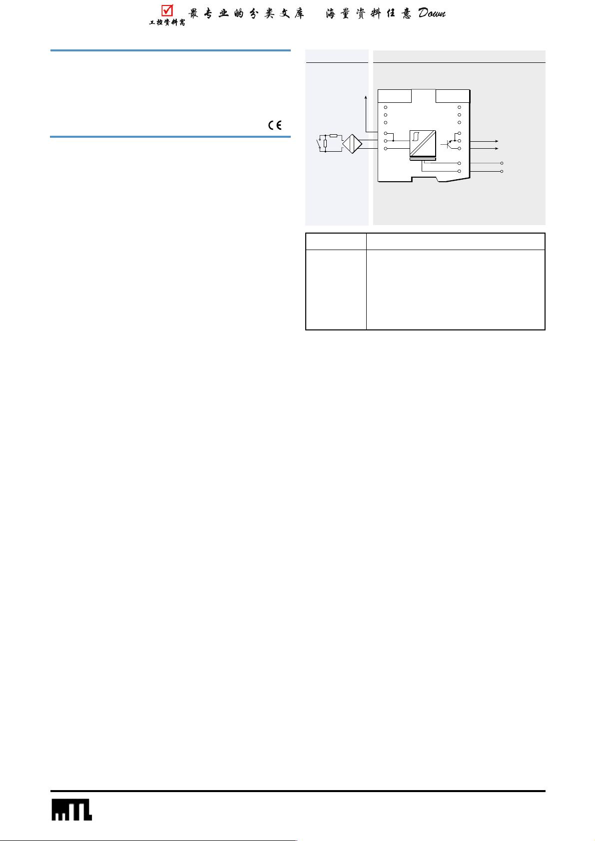
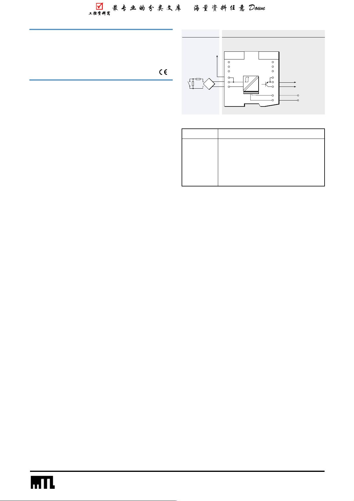
Terminal Function
1 Input –ve
2 Input +ve
3 Earth leakage detection
10, 11 Output –ve
12 Output +ve
13 Supply –ve
14 Supply +ve
Hazardous area Safe area
The MTL5012 enables a solid-state output in the safe area to be
controlled by a switch or proximity detector located in the hazardous
area. Independent output phase reversal and line fault detection are
provided.
SPECIFICATION
See also common specification
Number of channels
One
Location of switch
Zone 0, IIC, T6 hazardous area
Div. 1, Group A hazardous location
Location of proximity detector
Zone 0, IIC, T4–6 hazardous area if suitably certified
Div. 1, Group A hazardous location
Safe-area output
Floating solid-state output compatible with logic circuits
Hazardous-area input
Input conforming to NAMUR/DIN 19234 standards for proximity
detectors
Voltage applied to sensor
7 to 9V from 1kΩ ±10%
Input/output characteristics
Normal (reverse) phase:
output on (off) if I
in
>2.1mA or R
in
<2kΩ
output off (on) if I
in
<1.2mA or R
in
>10kΩ
Hysteresis: 200µA, typical
Line fault detection (LFD)
User-selectable. Line faults are indicated by an LED. A detected
line fault switches off the output.
Open-circuit alarm on if I
in
<50µA
Open-circuit alarm off if I
in
>150µA
Short-circuit alarm on if R
in
<100Ω
Short-circuit alarm off if R
in
>360Ω
Note: Resistors must be fitted when using the LFD facility with a contact input
500
Ω
to 1k
Ω
in series with switch
20k
Ω
to 25k
Ω
in parallel with switch
Phase reversal
User-selectable
Output characteristics
Operating frequency: dc to 5kHz
Max. off-state voltage: 35V
Max. off-state leakage current: 10µA
Max. on-state voltage drop: 1 + (0.13 x current in mA) V
Max. on-state current: 50mA
LED indicators
Green: power indication
Yellow: status (on when output is on)
Red: LFD indication (on when line fault detected)
Maximum current consumption
28mA at 20V
30mA at 24V
32mA at 35V
Maximum power dissipation
0.8W at 24V
1.2W at 35V
Isolation
250V ac or dc between power supply, input and output
Safety description
10.5V, 800Ω, 14mA, U
m
= 250V rms or dc
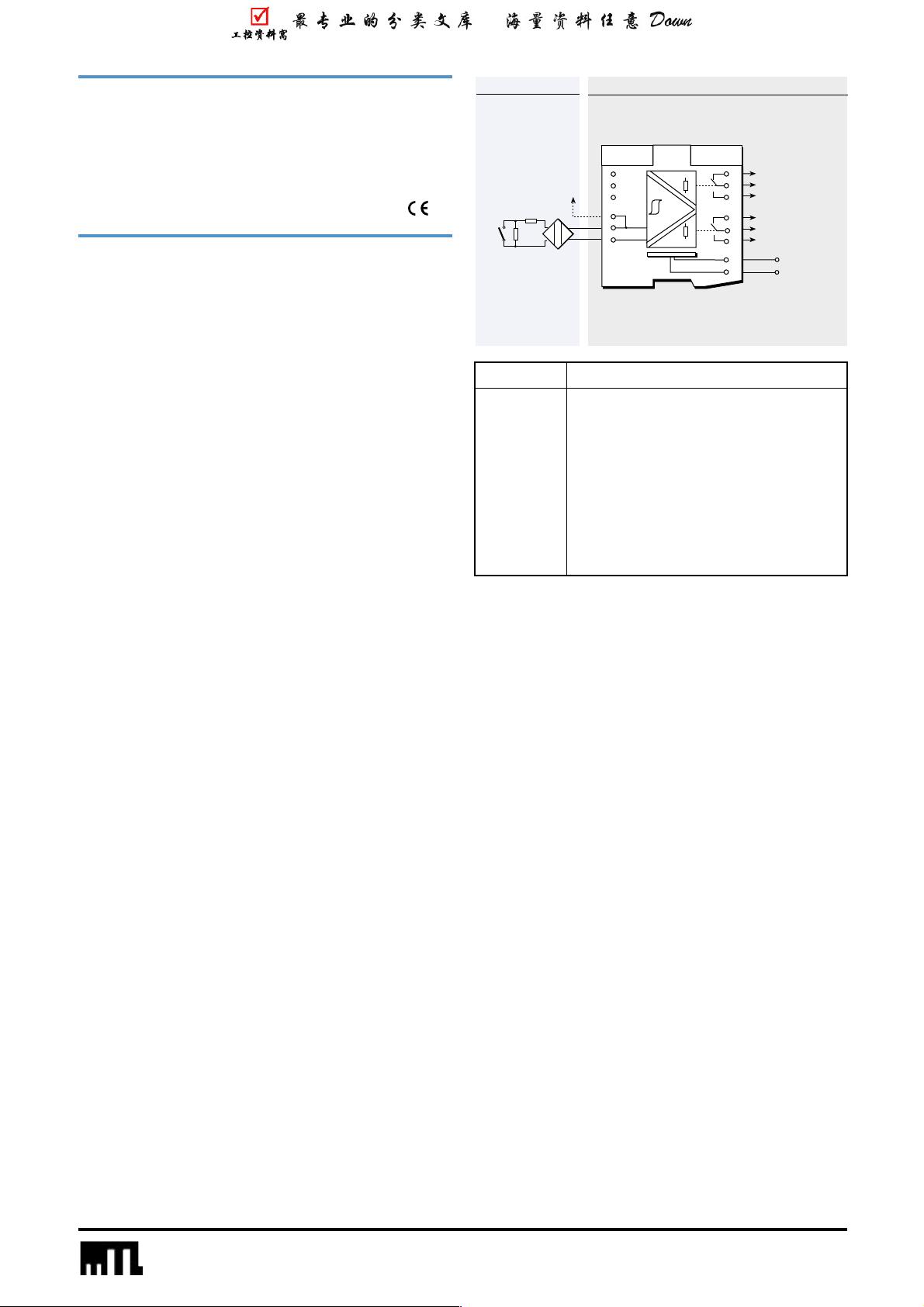
Resistors only
required for line
fault detection
6
5
4
3
2
1
7
8
9
10
11
12
13
14
Vs–
Vs+
20 to 35V dc
22kΩ
680Ω
+
–
To earth
leakage
detector
–
+
Output
剩余45页未读,继续阅读
2021-04-07 上传
2023-05-25 上传
2023-08-11 上传
2023-08-10 上传
2024-04-16 上传
2023-03-28 上传
2023-09-22 上传
2023-03-29 上传

weixin_38660802
- 粉丝: 2
- 资源: 958
 我的内容管理
展开
我的内容管理
展开


最新资源
- 多模态联合稀疏表示在视频目标跟踪中的应用
- Kubernetes资源管控与Gardener开源软件实践解析
- MPI集群监控与负载平衡策略
- 自动化PHP安全漏洞检测:静态代码分析与数据流方法
- 青苔数据CEO程永:技术生态与阿里云开放创新
- 制造业转型: HyperX引领企业上云策略
- 赵维五分享:航空工业电子采购上云实战与运维策略
- 单片机控制的LED点阵显示屏设计及其实现
- 驻云科技李俊涛:AI驱动的云上服务新趋势与挑战
- 6LoWPAN物联网边界路由器:设计与实现
- 猩便利工程师仲小玉:Terraform云资源管理最佳实践与团队协作
- 类差分度改进的互信息特征选择提升文本分类性能
- VERITAS与阿里云合作的混合云转型与数据保护方案
- 云制造中的生产线仿真模型设计与虚拟化研究
- 汪洋在PostgresChina2018分享:高可用 PostgreSQL 工具与架构设计
- 2018 PostgresChina大会:阿里云时空引擎Ganos在PostgreSQL中的创新应用与多模型存储
