
TS5USBA224
www.ti.com.cn
ZHCS273A –OCTOBER 2010– REVISED OCTOBER 2010
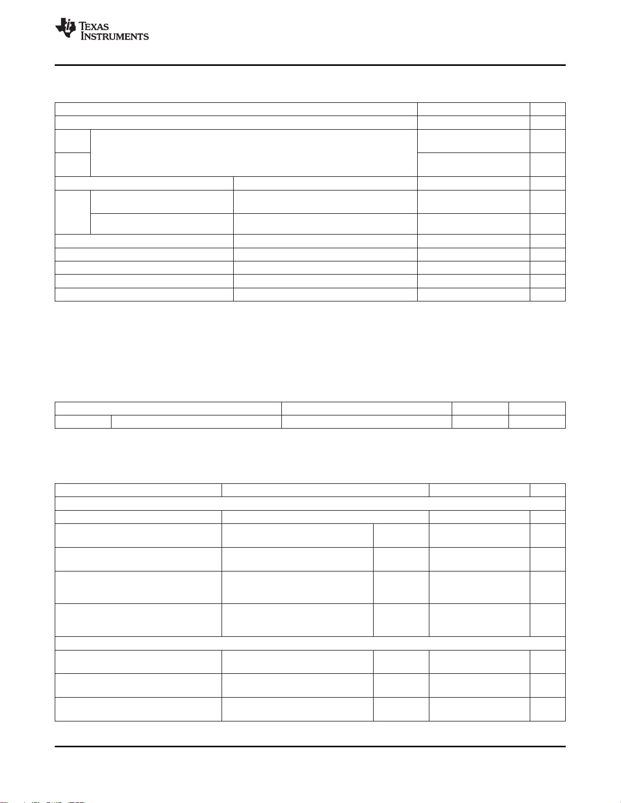
ABSOLUTE MAXIMUM RATINGS
(1)(2)
over operating free-air temperature range (unless otherwise noted)
MIN MAX UNIT
V
AUDIO
Supply voltage range
(3)
–0.5 6.5 V
V
D+
–0.5 6.5 V
V
D–
Analog voltage Range
(3)
V
R
V
AUDIO
– 6.5 V
AUDIO
+ 0.5 V
V
L
I
K
Analog port diode current V
D+
, V
D–
< 0 –50 mA
I
D+
, I
D–
V
D+
, V
D–
= 0 to V
AUDIO
,
ON-state switch current –100 100 mA
I
R
, I
L
V
R
, V
L
V
D+/R
, V
D–/L
= V
AUDIO
– 5.5 V to V
AUDIO
I
D+/R
ON-state peak switch current
(4)
–200 200
I
D–/L
V
I
Digital input voltage range –0.5 6.5 V
I
IK
Digital logic input clamp current
(3)
V
I
< 0 –50 mA
I
AUDIO
Continuous current through V
AUDIO
100 mA
I
GND
Continuous current through GND –100 mA
T
stg
Storage temperature range –65 150 °C
(1) Stresses beyond those listed under "absolute maximum ratings" may cause permanent damage to the device. These are stress ratings
only, and functional operation of the device at these or any other conditions beyond those indicated under "recommended operating
conditions" is not implied. Exposure to absolute-maximum-rated conditions for extended periods may affect device reliability.
(2) The algebraic convention, whereby the most negative value is a minimum and the most positive value is a maximum.
(3) All voltages are with respect to ground, unless otherwise specified.
(4) Pulse at 1-ms duration <10% duty cycle.
PACKAGE THERMAL IMPEDANCE
(1)
over operating free-air temperature range (unless otherwise noted)
PARAMETER TEST CONDITIONS TYP UNIT
θ
JA
Package thermal impedance RSW package 175 °C/W
(1) The package thermal impedance is calculated in accordance with JESD 51-7.
ELECTRICAL CHARACTERISTICS
T
A
= –40°C to 85°C, typical values are at V
AUDIO
= 3.3 V, T
A
= 25°C (unless otherwise noted)
PARAMETER TEST CONDITIONS MIN TYP MAX UNIT
USB SWITCH
V
D+
,V
D–
Analog voltage range 0 5.5 V
r
on
ON-state resistance V
AUDIO
= 3 V, V
BUS
= 5 V, V
ASEL
= 0 V, Switch ON 4 7 Ω
V
D+/D–
= 0 V, 0.4 V, I
ON
= –8 mA
Δr
on
ON-state resistance match V
AUDIO
= 3 V, V
BUS
= 5 V, V
ASEL
= 0 V, Switch ON 0.3 Ω
between channels
V
D+/D–
= 0 V, 0.4 V, I
ON
= –8 mA
I
D+(OFF)
D+ ,D- V
AUDIO
= 3.6 V, V
BUS
= 0 V, V
ASEL
= 3.6 Switch OFF ±50 nA
V,
I
D–(OFF)
OFF leakage current
V
D+
,V
D–
= 0.3 V, V
D+/R
,V
D–/L
= 0.3 V
I
D+(ON)
D+ ,D– V
AUDIO
= 3.6 V, V
BUS
= 5 V, V
ASEL
= 0 Switch ON ±50 nA
V,
I
D–(ON)
ON leakage current
V
D+
,V
D–
= 0.3 V, V
D+/R
= Open
AUDIO SWITCH
V
R
,V
L
Analog voltage range V
AUDIO
V
AUDIO
V
– 5.5
r
on
ON-state resistance V
AUDIO
= 3 V, V
BUS
= 0 V, V
ASEL
= 3 V, Switch ON 3 5 Ω
V
L/R
= –2 V, 0 V, 0.7 V, I
ON
= –26 mA
Δr
on
ON-state resistance match V
AUDIO
= 3 V, V
BUS
= 0 V, V
ASEL
= 3 V, Switch ON 0.3 Ω
between channels
V
L/R
= 0.7 V, I
ON
= –26 mA
版权 © 2010, Texas Instruments Incorporated 5
剩余22页未读,继续阅读


