
Mathematical Problems in Engineering
P
0
P
1
P
2
𝜃
1
𝜃
2
−−→
N
P
0
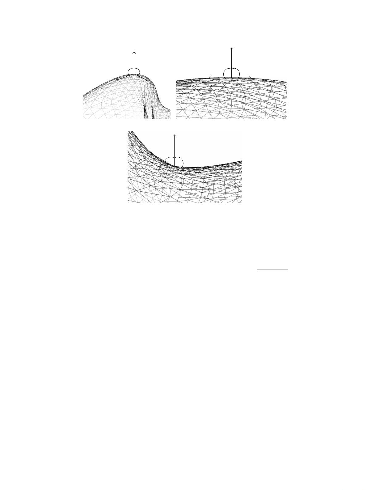
(a) Prongness <0
P
0
P
1
P
2
𝜃
1
𝜃
2
−−→
N
P
0
(b) Prongness =0
P
0
P
1
P
2
𝜃
1
𝜃
2
−−→
N
P
0
(c) Prongness >0
F : e prongness value is negative for protrusive vertices and positive for concave vertices.
2.1. Selecting Prongs. e rst step of watermark embedding
is to select prominent feature vertices, or “prongs”, from
D meshes. Feature vertices are common descriptors of D
surfaces, which have been used for mesh segmentation [,
]andobjectrecognition[]. In this application, we require
feature vertices to be protrusive because protrusive regions
contain most information of the shape []. If an attacker
removes all protrusive regions, most probably he/she would
obtain a meaningless shape. We associate a prongness value to
each vertex. In this paper, the prongness value is an indicator
of how protrusive a vertex could be. Prongness value is
calculated by adding up the dot products between the normal
direction of this vertex and the vector from this vertex to its
nearest neighbors:
Prongness
0
=
𝑃∈𝑉
1
(
𝑃
0
)
→
0
⋅
→
𝑃
0
→
0
→
𝑃
0
,
()
where
→
𝑃
0
represents the normal direction of vertex
0
and
1
(
0
) is the set of vertices which are close to vertex
0
in
geodesic distance. Various methods have been proposed to
calculate normal directions in D meshes [, ]. In this
paper,weuseasimpleandcommonone.erststepis
tocalculatethesurfacenormal
→
𝑗
at each polygon from
the neighborhood of
0
. e surface normal of a polygon is
calculated as the vector product of the orientations of two of
its edges divided by the vector length. e normal direction at
vertex
0
is taken as the average of surface normal directions
corresponding to its adjacent polygons; that is,
→
𝑃
0
=
∑
𝑉
𝑗
∈𝑉
(
𝑃
0
)
→
𝑗
,
()
where (
0
) is the set of vertices which are connected with
0
,andis the total number of these vertices.
e algorithm to calculate geodesic distances was pre-
sented by Dijkstra []. In , Kimmel and Sethian pro-
posed the fast marching algorithm running in complexity
(log )[]. e fast marching algorithm was modied by
our previous work to increase its speed [, ]. In this paper,
we use the method of our previous work to calculate geodesic
distances. e prongness calculation is to add up the cosines
between
→
𝑃
0
and
→
0
for all ’s which are geodesically close
to
0
,asshowninFigure .
Prongs are selected as local minimums of prongness
values. In this paper, a vertex is selected as a prong if it takes
the lowest prongness value compared with its neighborhood
vertices. We use
2
(
0
)to represent the set of
0
’s neighbor-
hood vertices which need to be compared with
0
.Wechoose
2
(
0
)as the set of the rst
2
vertices which are close to
0
in geodesic distance. In other words, a vertex is selected as a
prong if it has the lowest prongness value among its closest
2
vertices in geodesic distance.
Figure shows the selected prongs of the bunny, head,
and hand models. Each prong is represented as a red point
onthemesh.erearealsoprongsatthebackofeachmodel,
which are not shown here. We choose
1
=200,whichmeans
that we take the closest vertices to calculate the prongness
剩余12页未读,继续阅读

weixin_38663151
- 粉丝: 3
- 资源: 897
 我的内容管理
展开
我的内容管理
展开


最新资源
- 十种常见电感线圈电感量计算公式详解
- 军用车辆:CAN总线的集成与优势
- CAN总线在汽车智能换档系统中的作用与实现
- CAN总线数据超载问题及解决策略
- 汽车车身系统CAN总线设计与应用
- SAP企业需求深度剖析:财务会计与供应链的关键流程与改进策略
- CAN总线在发动机电控系统中的通信设计实践
- Spring与iBATIS整合:快速开发与比较分析
- CAN总线驱动的整车管理系统硬件设计详解
- CAN总线通讯智能节点设计与实现
- DSP实现电动汽车CAN总线通讯技术
- CAN协议网关设计:自动位速率检测与互连
- Xcode免证书调试iPad程序开发指南
- 分布式数据库查询优化算法探讨
- Win7安装VC++6.0完全指南:解决兼容性与Office冲突
- MFC实现学生信息管理系统:登录与数据库操作
资源上传下载、课程学习等过程中有任何疑问或建议,欢迎提出宝贵意见哦~我们会及时处理!
点击此处反馈


