
Aardvark I
2
C/SPI Embedded Systems Interface
SS
SCLK
MISO
MOSI
MISO
MOSI
MISO
MOSI
t
d
t
b
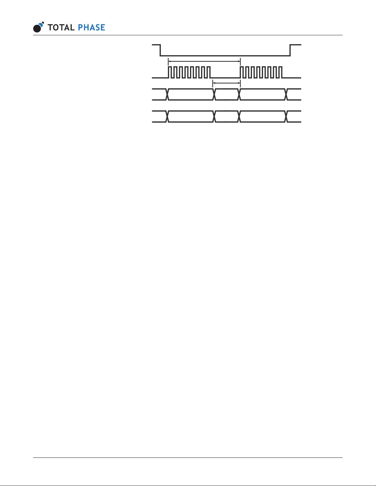
Figure 8: SPI Byte Timing
t
d
is the setup time between SPI bytes and t
b
is the total byte-to-byte time.
Speeds
The Aardvark SPI master can operate at bitrates of 125 kHz, 250 kHz, 500 kHz, 1 MHz, 2
MHz, 4 MHz, and 8 MHz. The power-on default bitrate is 1 MHz. The quoted bitrates are only
achievable within each individual byte and does not extend across bytes. There is approximately
9
˘
aµs of setup time required in between each byte which results in a total transmission period
of the byte transmission time plus 9 µs.
The Aardvark SPI slave can operate at any bitrate up to 4 Mbps. However, for correct trans-
mission from slave to master there must be at least 4 µs delay between the end of byte n and
start of byte n+1 for the MISO data to be setup properly for byte n+1. Otherwise, the Aardvark
adapter will simply return the data it just received. Likewise, for correct reception of data by the
slave, there must be at least 10 µs between the start of byte n and the start of byte n+1.
Similarly, when the Aardvark adapter is configured to act as an SPI slave, and the slave select is
pulled high to indicate the end of a transaction, there is a data processing overhead of sending
the transaction to the PC host. As such, if the SPI master sends a subsequent transaction
in rapid succession to the Aardvark slave, the data received by the Aardvark slave may be
corrupted. There is no precise value for this minimum inter-transaction time, but a suggested
spacing is approximately 100–200 µs.
Pin Driving
When the SPI interface is activated as a master, the slave select line (SS) is actively driven low.
The MOSI and SCK lines are driven as appropriate for the SPI mode. After each transmission is
complete, these lines are returned to a high impedance state. This feature allows the Aardvark
adapter, following a transaction as a master SPI device, to be then reconnected to another
SPI environment as a slave. The Aardvark adapter will not fight the master lines in the new
environment.
Consequently, any SPI slave target to which the Aardvark adapter is interfaced must have a
pull-up resistor on its slave select line, preventing fluttering of the voltage when the Aardvark
adapter stops driving the signal. It is also advisable that every slave also have passive pull-ups
on the MOSI and SCK lines. These pull-up resistors can be relatively weak — 100k should be
adequate.
As a slave, the MOSI, SCK, and SS lines are configured as an input and the MISO line is
www.totalphase.com 11


剩余62页未读,继续阅读

hsg269477074
- 粉丝: 4
- 资源: 5
 我的内容管理
收起
我的内容管理
收起
- 我的资源
快来上传第一个资源
 我的收益 登录查看自己的收益
 我的积分
登录查看自己的积分
我的积分
登录查看自己的积分
 我的C币
登录后查看C币余额
我的C币
登录后查看C币余额
 我的收藏
我的收藏  我的下载
我的下载  下载帮助
下载帮助

会员权益专享


最新资源
- 谷歌文件系统下的实用网络编码技术在分布式存储中的应用
- 跨国媒体对南亚农村社会的影响:以斯里兰卡案例的社会学分析
- RFM2g接口驱动操作手册:API与命令行指南
- 基于裸手的大数据自然人机交互关键算法研究
- ABAQUS下无人机机翼有限元分析与局部设计研究
- TCL基础教程:语法、变量与操作详解
- FPGA与数字前端面试题集锦:流程、设计与Verilog应用
- 2022全球互联网技术人才前瞻:元宇宙驱动下的创新与挑战
- 碳排放权交易实战手册(第二版):设计与实施指南
- 2022新经济新职业洞察:科技驱动下的百景变革
- 红外与可见光人脸融合识别技术探究
- NXP88W8977:2.4/5 GHz 双频 Wi-Fi4 + Bluetooth 5.2 合体芯片
- NXP88W8987:集成2.4/5GHz Wi-Fi 5与蓝牙5.2的单芯片解决方案
- TPA3116D2DADR: 单声道数字放大器驱动高达50W功率
- TPA3255-Q1:315W车载A/D类音频放大器,高保真、宽频设计
- 42V 输入 5A 降压稳压器 TPS54540B-Q1 的特点和应用
资源上传下载、课程学习等过程中有任何疑问或建议,欢迎提出宝贵意见哦~我们会及时处理!
点击此处反馈


