
ON Semiconductor
http://onsemi.com
85
CHAPTER 7
Bridgeless PFC
Introduction
The need for higher efficiencies from the PFC stage has led the circuit designers to look closely at all sections of the circuit
and develop possible lower loss alternatives. One section that contributes significantly to the losses is the input bridge rectifier.
As a result, the alternatives to eliminate the diode bridge or convert it into a dual-use circuit have been explored for many years.
This elimination/conversion of diode bridge brings about its own set of challenges. This chapter provides a more in-depth look
at the bridgeless techniques and works through a design example for an 800-W bridgeless PFC converter.
Why remove the bridge?
EMI
Filter
AC
Line
PFC
Stage
D
1
D
2
D
3
D
4
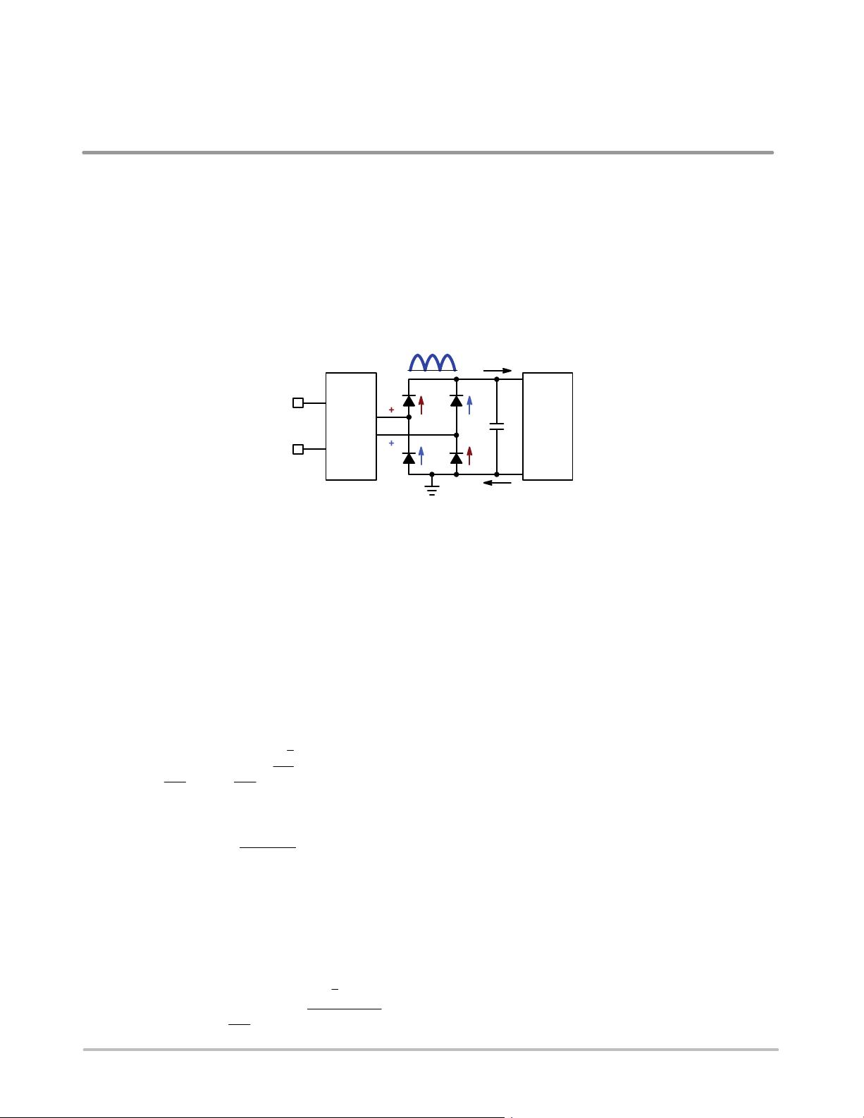
Figure 7−1. The Input Current Flows Through Two Diodes
Figure 7−1 portrays the diode bridge that is usually inserted between the EMI filter and the PFC stage. This bridge rectifies
the line voltage to feed the PFC stage with a rectified sinusoid input voltage. It is well known that as a result of this structure,
the input current must flow through two diodes before being processed by the PFC boost stage:
♦
For one line half-wave, D1 and D4 conduct (red arrows of Figure 7−1)
♦
For the other one, D2 and D3 convey the current (blue arrows of Figure 7−1)
As a matter of fact, two diodes of the bridge are permanently inserted in the current path. Unfortunately, these components
exhibit a forward voltage that leads to conduction losses.
The mean value of the current seen by the bridge is the line current averaged over one half−line cycle. Hence we can write
the following equation:
ǂ
I
bridge
ǃ
T
line
2
+
ǂ
I
in
(t)
ǃ
T
line
2
+
22
Ǹ
p
@ I
in(rms)
(eq. 1)
The line rms current can be easily expressed as a function of the power and of the line voltage:
I
in(rms)
+
P
out
h @ V
in(rms)
(eq. 2)
Where:
♦
P
out
is the output power
♦
h is the efficiency
♦
V
in(rms)
is the rms line voltage
Since two diodes permanently see the average input current, the bridge consumes a power that can be computed as follows:
P
bridge
+ 2 @ V
f
@
ǂ
I
bridge
ǃ
T
line
2
^ 2 @ V
f
@
22
Ǹ
@ P
out
h @ p @ V
in(rms)
(eq. 3)

weixin_38744375
- 粉丝: 372
- 资源: 2万+
 我的内容管理
收起
我的内容管理
收起
- 我的资源
快来上传第一个资源
 我的收益 登录查看自己的收益
 我的积分
登录查看自己的积分
我的积分
登录查看自己的积分
 我的C币
登录后查看C币余额
我的C币
登录后查看C币余额
 我的收藏
我的收藏  我的下载
我的下载  下载帮助
下载帮助

会员权益专享


最新资源
- 计算机系统基石:深度解析与优化秘籍
- 《ThinkingInJava》中文版:经典Java学习宝典
- 《世界是平的》新版:全球化进程加速与教育挑战
- 编程珠玑:程序员的基础与深度探索
- C# 语言规范4.0详解
- Java编程:兔子繁殖与素数、水仙花数问题探索
- Oracle内存结构详解:SGA与PGA
- Java编程中的经典算法解析
- Logback日志管理系统:从入门到精通
- Maven一站式构建与配置教程:从入门到私服搭建
- Linux TCP/IP网络编程基础与实践
- 《CLR via C# 第3版》- 中文译稿,深度探索.NET框架
- Oracle10gR2 RAC在RedHat上的安装指南
- 微信技术总监解密:从架构设计到敏捷开发
- 民用航空专业英汉对照词典:全面指导航空教学与工作
- Rexroth HVE & HVR 2nd Gen. Power Supply Units应用手册:DIAX04选择与安装指南
资源上传下载、课程学习等过程中有任何疑问或建议,欢迎提出宝贵意见哦~我们会及时处理!
点击此处反馈


