
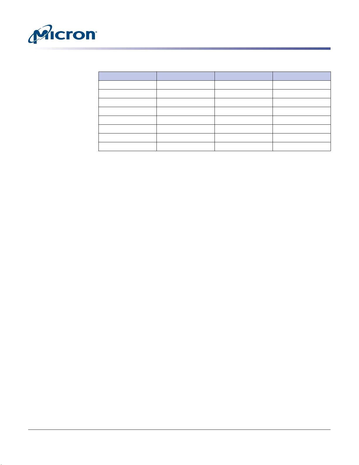
Table 5: Scrambler Logic Seed Values
Lane Seed Value Lane Seed Value
0 15'h4D56 8 15'h3EB3
1 15'h47FF 9 15'h2769
2 15'h75B8 10 15'h4580
3 15'h1E18 11 15'h5665
4 15'h2E10 12 15'h6318
5 15'h3EB2 13 15'h6014
6 15'h4302 14 15'h077B
7 15'h1380 15 15'h261F
Note:
1. Scrambler logic seed values for lanes 0–7 are the same with full-width and half-width
configurations.
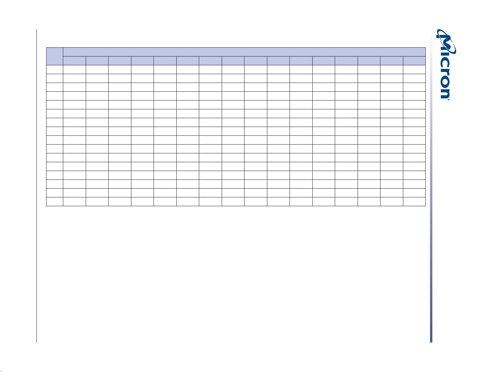
Table 6 contains a series of NULL packets to illustrate how the scrambler operates on
each lane. The Lane 0 LFSR starts with seed value 0xCD56. This is the 15-bit seed value
from Table 5 (15'h4D56) with the next (16th) bit of the PRBS included to enable scram-
bling of 16 data payload bits per clock cycle; the scrambler PRBS is calculated at 16 bits
per clock cycle. The scrambler LFSR[15:0] is bitwise exclusive-OR'ed with data[15:0] to
generate scrambled data. When NULLs, or all zeroes payload data per lane, are scram-
bled, the continual exclusive-or with (payload) zero causes the scrambled data to be
identical to the scrambler LFSR value each clock cycle. As a result, the list of the scram-
bler LFSR sequence is also the list of scrambled data when the payload data is all
NULLs.
Hybrid Memory Cube – HMC Gen2
Logical Sub-Block of Physical Layer
09005aef8462cb46
hmc_gen2.pdf - Rev. H 2/18 EN
16
Micron Technology, Inc. reserves the right to change products or specifications without notice.
© 2018 Micron Technology, Inc. All rights reserved.

剩余104页未读,继续阅读

搬砖民工9832
- 粉丝: 0
- 资源: 4
 我的内容管理
展开
我的内容管理
展开


最新资源
- AirKiss技术详解:无线传递信息与智能家居连接
- Hibernate主键生成策略详解
- 操作系统实验:位示图法管理磁盘空闲空间
- JSON详解:数据交换的主流格式
- Win7安装Ubuntu双系统详细指南
- FPGA内部结构与工作原理探索
- 信用评分模型解析:WOE、IV与ROC
- 使用LVS+Keepalived构建高可用负载均衡集群
- 微信小程序驱动餐饮与服装业创新转型:便捷管理与低成本优势
- 机器学习入门指南:从基础到进阶
- 解决Win7 IIS配置错误500.22与0x80070032
- SQL-DFS:优化HDFS小文件存储的解决方案
- Hadoop、Hbase、Spark环境部署与主机配置详解
- Kisso:加密会话Cookie实现的单点登录SSO
- OpenCV读取与拼接多幅图像教程
- QT实战:轻松生成与解析JSON数据
资源上传下载、课程学习等过程中有任何疑问或建议,欢迎提出宝贵意见哦~我们会及时处理!
点击此处反馈


