
AP0101AT HDR: Image Signal Processor (ISP)
Features
ON Semiconductor Confidential and Proprietary
AP0101AT_DS Rev. D Pub. 3/15 EN 1 ©Semiconductor Components Industries, LLC,2012
AP0101AT High-Dynamic Range (HDR)
Image Signal Processor (ISP)
AP0101AT Datasheet, Rev. D
For the latest product datasheet revision, please visit www.aptina.com
Features
• Supports ON Semiconductor sensors with up to
1.2 Mp (1280x960)
• 45 fps at 1.2 Mp, 60 fps at 720p
• Optimized for operation with HDR sensors
• Color and gamma correction
• Auto exposure, auto white balance, 50/60 Hz flicker
avoidance
• Adaptive Local Tone Mapping (ALTM)
• Test Pattern Generator
• Two-wire serial programming interface
• Interface to low-cost Flash or EPROM through SPI
bus (to configure and load patches)
• High-level host command interface
• Standalone operation supported
• Up to 5 GPIO
•Fail-safe IO
• Multi-Camera synchronization support
•Dual Band IR filter support
Applications
• Automotive surround, rear and front view cameras
• Blind spot/side mirror replacement cameras
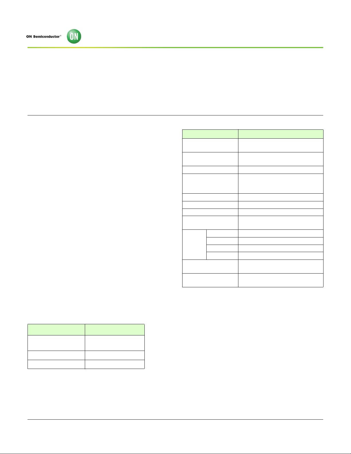
Ordering Information
Table 1: Available Part Numbers
Part Number Description
AP0101AT2L00XPGA0
81-ball VFBGA Package
Production Part
AP0101AT2L00XPGAD-E Demo kit
AP0101AT2L00XPGAH-E Headboard
Notes: 1. 20-bit in one pixel clock format is only available in
SMPTE mode with the use of 4 GPIOs.
2. With input clock below 10 MHz, the two wire
serial interface is supported only up to 100 KHz
3. Maximum frame rate depends on output inter-
face and data format configuration used.
4. 720p HDR 60 fps 74.25 MHz YCbCr_422_16
Table 2: Key Performance Parameters
Parameter Value
Primary camera
interface
Parallel
Primary camera input
format
RAW12 Linear/Companded Bayer
data
Output interface Up to 20-bit Parallel
1
Output format
YUV422 8-bit,10-bit, and
SMPTE296M
10-, 12-bit tone-mapped Bayer
Maximum resolution 1280x960 (1.2 Mp)
Input clock range
2
6-30 MHz
Maximum frame rate
3
45 fps at 1.2 Mp, 60 fps at 720p
Maximum output clock
frequency
Parallel clock up to 84 MHz
Supply
voltage
V
DDIO_S 1.8 or 2.8 V nominal
VDDIO_H 2.5 or 3.3 V nominal
V
DD_REG 1.8V nominal
V
DDIO_OTPM 2.5 or 3.3 V nominal
Operating temperature
(ambient - T
A
)
-40°C to +105°C
Typical power
consumption
4
130 mW


剩余44页未读,继续阅读

qq_39777113
- 粉丝: 0
- 资源: 29
 我的内容管理
收起
我的内容管理
收起
- 我的资源
快来上传第一个资源
 我的收益 登录查看自己的收益
 我的积分
登录查看自己的积分
我的积分
登录查看自己的积分
 我的C币
登录后查看C币余额
我的C币
登录后查看C币余额
 我的收藏
我的收藏  我的下载
我的下载  下载帮助
下载帮助

会员权益专享


最新资源
- 基于Springboot的医院信管系统
- 基于Springboot的冬奥会科普平台
- 基于Springboot的社区医院管理服务系统
- 基于Springboot的实习管理系统
- TI-TCAN1146.pdf
- 基于Springboot的留守儿童爱心网站
- S32K3XXRM.pdf
- Ansible Automation Platform 快速安装指南 v3.8.1
- Ansible Tower 发行注记 v3.8.1-76页
- C语言笔记-考研版(进阶)
- Design_of_Analog_CMOS_Integrated_Circuit20200602-85440-9wt61m-with-cover-page-v2 (1).pdf
- Ansible Automation Platform 安装和参考指南 v3.8.1-59页
- 浅析5G技术在工业互联网领域的应用研究
- 查重17 岑彩谊-基于otn技术的本地承载网-二稿 .docx
- 自考计算机应用基础知识点.doc
- 数据库系统安全、技术操作规程.doc
资源上传下载、课程学习等过程中有任何疑问或建议,欢迎提出宝贵意见哦~我们会及时处理!
点击此处反馈


