没有合适的资源?快使用搜索试试~ 我知道了~
首页FANUC A06B-6091-H0025: 动态备份模块功能说明与维护更新
A06B-6091-H0025 是一款发那科(FANUC)的备用电源模块,专为发那科伺服放大器α系列设计,其型号为A-53866E-464。这款模块的主要功能是为系统提供在电力故障时的备份支持,确保关键设备的持续运行。它于2005年5月首次发布,作为一个可选功能单元,旨在增强系统的稳定性和可靠性。 该模块的主要作用是在主电源断电的情况下,临时存储和分配必要的能量,以维持伺服系统的正常工作,特别是在自动化生产线或精密控制设备中,这能够避免生产中断并提高整体运营效率。此外,该模块还包含维护部分的注意事项,强调了定期检查和更换关键部件对于确保模块性能和延长使用寿命的重要性。 在A-53866E-464的描述文档中,提到了多个版本,包括B-65162/03-04、B-65162/03-08、B-65162/03-10以及A-53866-401和A-53866-405等,这些版本分别代表了不同的修订和补充,反映了技术规格和操作指南的不断更新和完善。例如,B-65162系列可能包含了安全操作指南、故障排查方法和最新维修策略等内容。 值得注意的是,尽管手册尽力描述了各种情况下的操作和维护,但考虑到实际应用的复杂性和多样性,某些特定的操作可能无法在文档中详尽列出,因此,特别指出的事项并不意味着绝对不可能,而是需要用户根据具体环境和条件灵活判断和处理。用户在操作时应遵循手册的建议,并结合实际情况,确保安全合规。 A06B-6091-H0025发那科备用电源执行系统是一个重要的设备,它在工业自动化领域扮演着关键的角色,为应对突发的电力中断提供了可靠的保障。通过了解其技术规格、功能特点以及维护要求,用户可以更有效地管理并优化系统的性能。
资源详情
资源推荐
EDIT.
FANUC LTD
SHEET
DRAW. NO.
CUST.
TITLE
15
/
93
DESCRIPTIONDESIG.DATE
Power Failure Backup Module
Descriptions
A-53866E-464
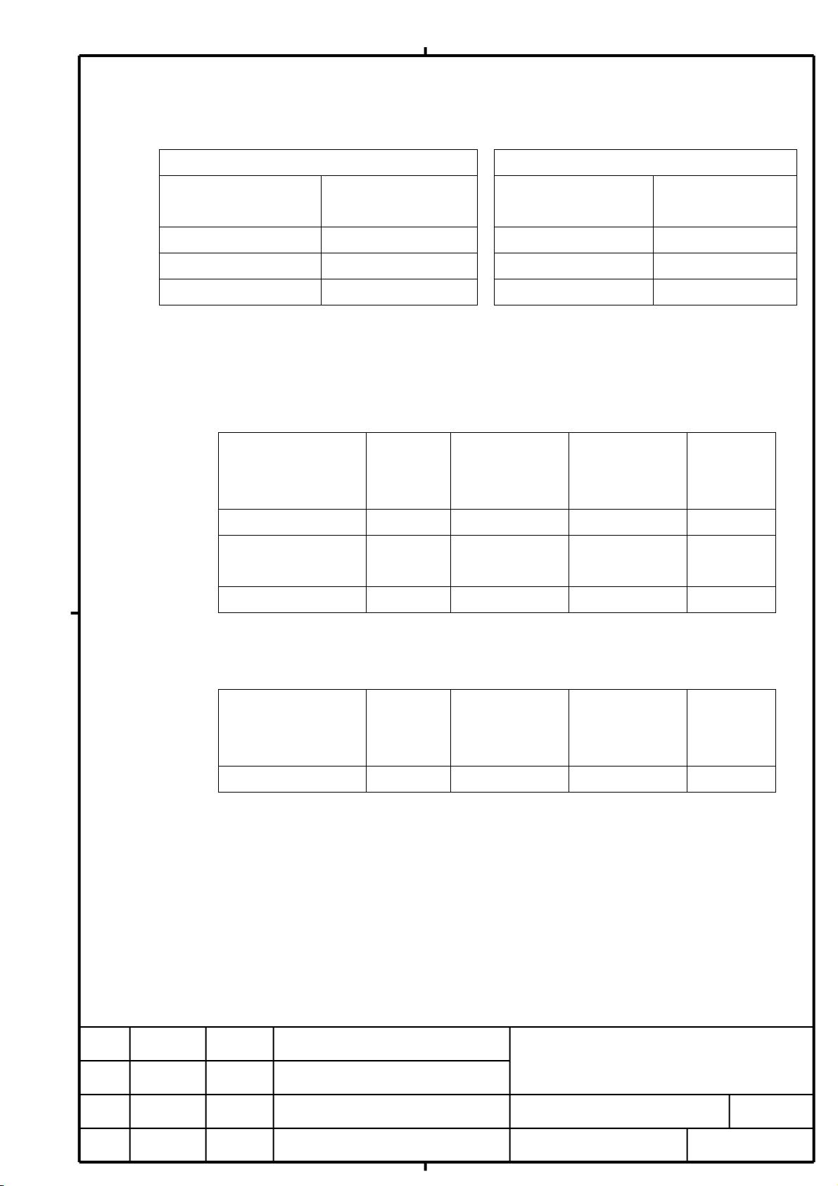
(3) Energy supply capability in the event of a power failure: Depends on the input power
voltage of the PSM and the number of sub modules C connected.
Energy amount per one sub module C
A06B-6077-H010 (for 200V) A06B-6083-H245 (for400V)
PSM input voltage
V1
Energy amount
W1
PSM input voltage
V1
Energy amount
W1
AC170V 478J AC340V 330J
AC200V 755J AC400V 530J
240 VAC 1195J AC480V 850J
Up to eight sub modules C can be connected. For selection information, see Section
8.2.
(4) Maximum regeneration capability (resistor regeneration): Depends on the type of sub
module R and the number of sub modules R connected.
200V input type
Type of sub module R
No. of sub
modules R
connected
Regeneration
capability <1>
Regeneration
capability <2>
Remarks
A06B-6089-H712 1 20kW 100kJ
A06B-6089-H712 2 40kW 200kJ Parallel
connection
A06B-6077-H020 1 40kW 80kJ
* The upper limit on the number of sub modules that can be connected is 2 for
the A06B-6089-H712 and 1 for the A06B-6077-H020.
400V input type
Type of sub module R
No. of sub
modules R
connected
Regeneration
capability <1>
Regeneration
capability <2>
Remarks
A06B-6077-H020 1 40kW 80kJ
* The upper limit on the number of sub modules that can be connected is 1.
Regeneration capability <1>: Maximum output of the motor that can be decelerated
in the event of a power failure
Regeneration capability <2>: Product of the motor output [kW] during deceleration
and the deceleration time [sec]
For information on selecting sub module R, see Section 8.1.
EDIT.
FANUC LTD
SHEET
DRAW. NO.
CUST.
TITLE
16
/
93
DESCRIPTIONDESIG.DATE
Power Failure Backup Module
Descriptions
A-53866E-464
(5) Control power supply
In the event of a power failure, supplies power to the control power supply inputs of
the amplifier and the CNC.
A06B-6077-H002 (200V input type)
Supplies power from connector CX13 to the control power supply inputs of the
amplifier and the CNC.
In normal operation, the200 VAC input to connector CX12 is output to connector
CX13.
In the event of a power failure, DC link voltage is output from connector CX13.
A06B-6091-H002 (400V input type)
Supplies power from connector CX28 to the control power supply inputs of the
amplifier and the CNC.
In normal operation, the200 VAC input to connector CX27 is output to connector
CX28.
In the event of a power failure, 300 VDC (voltage resulting from stepping down
the DC link voltage) is output from connector CX28.
Power supply capability of connectors CX13 and CX28
1000 VA maximum (including up to 300 VA to be supplied to the PSM control power supply)
Power switching time
After a power failure, when the output of connector CX13 or CX28 switches from200
VAC to direct-current voltage, an instantaneous break of up to 30 msec occurs (state
in which the output of connector CX13 and CX28 becomes 0 V).
To connector CX13 or CX28, connect a device that permits an instantaneous break of
30 msec.
Calculation of the power capacity
If the power capacity of the device to be connected to connector CX13 or CX28 is
indicated in units other than VA, determine the power capacity with the method
described below.
If power consumption is indicated in watts
Divide the consumption by the power factor, and you will get the power capacity. If the
power factor is unknown, assume the power factor to be 0.5.
If current consumption is indicated in amperes
Multiply the consumption by the working voltage of 200V, and you will get the power
capacity.
EDIT.
FANUC LTD
SHEET
DRAW. NO.
CUST.
TITLE
17
/
93
DESCRIPTIONDESIG.DATE
Power Failure Backup Module
Descriptions
A-53866E-464
For a switching power supply whose output current is known
Power capacity (VA) = Output voltage (V) x Output current (A)
÷ Power supply efficiency ÷ Power factor
If the efficiency and the power factor of the power supply
are not known, assume the
efficiency to be 0.85 and the power factor to be 0.5.
Measure to be taken if the power capacity of the device to be connected to connector CX13 or
CX28 exceeds 1000 VA
If the power capacity of the device to be connected to connector CX13 or CX28 exceeds 1000
VA, supply power from a UPS (uninterruptible power supply) to the device.
Even if you use a UPS, make sure that the control power to the PSM is supplied from the power
failure backup module (the control power supply input connector CX1A of the PSM is
connected to CX13 or CX28).
Backup of the control power to the dynamic brake module (DBM)
The dynamic brake module is driven on 200 VAC, and cannot be driven on direct current.
A system using a dynamic brake module requires a UPS with an output of 200 VAC for
the dynamic brake module. For connection information, see (18) in Section 5.2.
Specifications of the switching power supply to be connected to connector CX13 or CX28
<1> Input voltage range
170 VAC to 264 VAC (continuous)
240 VDC to 373 VDC (in power failure backup operation, 1 min. max.)
* Some types of switching power supply cannot be driven continuously on DC power
and, therefore, the specifications of some of these types state that they "cannot
be driven on DC power". Even such types can be driven on DC power if they satisfy
the time requirement for power failure backup (1 min. max.).
<2> Output current
Depends on the current consumption of the device to be connected.
<3> Operation at and below the input voltage specifications
The state in which the input voltage is 0 VDC to 240 VDC may keep for a maximum
of one minute. Even in this case, the switching power supply must be free from
damage and no voltage exceeding the specification range tolerable by the CNC and
others (24V+10%) may be output.
EDIT.
FANUC LTD
SHEET
DRAW. NO.
CUST.
TITLE
18
/
93
DESCRIPTIONDESIG.DATE
Power Failure Backup Module
Descriptions
A-53866E-464
<4> Retention time at an instantaneous power break
30 msec or greater
* Generally, the retention time given on the catalog is the value assumed when
the load factor is 100%. If the retention time requirement of 30 msec or greater
is not satisfied, the retention time can be extended by reducing the
load factor.
An example of a power supply that conforms to the above specifications is the LDA150B-24 of
COSEL Co., Ltd. (output: 150W).
(8) I/O input/output specifications
Rules for the control signals (EXPFL and *SYNC) for the power failure backup module and
the state signals (RDY, *PFL, and *ALM) output from the power failure backup module are
as follows:
Input signal rules
Pin 3 (EXPFL) of connector CX15 and pin A3 (*SYNC) of connector CX16
Contact capacity 24 VDC+10% 10mA
Voltage drop across contacts
at closed circuit
2 V or less (including a cable voltage drop)
Output signal rules
Pin B1 (*ALM), pin B2 (*PFL), and pin B3 (RDY) of connector CX16
ON-time maximum load current 200 mA or less including an instantaneous current
ON-time saturation voltage 1 V or less (at load current of 200 mA)
Withstand voltage 24 V+20% including an instantaneous voltage
OFF-time leak current 20 µA or less
Delay time 50 µsec
Protection function If the load current increases abnormally due to
the grounding of a cable or other reasons, the
protection function will operate and keep all
outputs OFF until the cause is removed.
For details of each signal, see Sections 6.5 and 6.6.
For details of the connection of connectors CX15 and CX16, see (6) and (7) of Section
5.2.
CAUTION
At a power failure, DC voltage is output from CX13 or CX28, instead of 200 VAC.
Never connect a device containing an AC fan motor or AC-driven electromagnetic
contactor to CX13 or CX28 because such a device may be burned out if DC voltage
EDIT.
FANUC LTD
SHEET
DRAW. NO.
CUST.
TITLE
19
/
93
DESCRIPTIONDESIG.DATE
Power Failure Backup Module
Descriptions
A-53866E-464
(7) Alarm handling
If an error occurs in the power failure backup module, the alarm number corresponding
to the error is indicated on the LED and connector CX16 outputs *ALM of 0.
Even if an alarm is generated, the power failure backup module does not forcibly
shut off power, so that the machine continues normal operation. If, however, an alarm
is generated in the power failure backup module, it will no longer perform power failure
backup operation in the event of a power failure. For this reason, if the power failure
backup module outputs *ALM of 0, immediately perform processing that stops the machine.
Also, shut off the PSM input, MCC, to protect the power failure backup module as soon
as you stop the machine.
For a description of alarms and their causes, see Section 6.4.
If, during machine operation, RDY changes from 1 to 0 although the power failure
backup module does not output an alarm signal (*ALM=1), this indicates that an error
has occurred in the power failure backup module.
If, during machine operation, RDY changes from 1 to 0, take the same action as that
when an alarm is generated in the power failure backup module.
(8) Total heat dissipation
Power failure backup module
A06B-6077-H002: 12W
A06B-6091-H002: 25W
Sub module C
A06B-6077-H010: 5W
A06B-6083-H245: 4W
Sub module R: No heat dissipated in the stationary state
(9) Environmental conditions
The environmental conditions for the αi series amplifier apply.
Refer to the Descriptions B-65282.
剩余92页未读,继续阅读
rensks
- 粉丝: 0
- 资源: 1
上传资源 快速赚钱
- 我的内容管理 展开
- 我的资源 快来上传第一个资源
- 我的收益 登录查看自己的收益
- 我的积分 登录查看自己的积分
- 我的C币 登录后查看C币余额
- 我的收藏
- 我的下载
- 下载帮助
最新资源
- 计算机人脸表情动画技术发展综述
- 关系数据库的关键字搜索技术综述:模型、架构与未来趋势
- 迭代自适应逆滤波在语音情感识别中的应用
- 概念知识树在旅游领域智能分析中的应用
- 构建is-a层次与OWL本体集成:理论与算法
- 基于语义元的相似度计算方法研究:改进与有效性验证
- 网格梯度多密度聚类算法:去噪与高效聚类
- 网格服务工作流动态调度算法PGSWA研究
- 突发事件连锁反应网络模型与应急预警分析
- BA网络上的病毒营销与网站推广仿真研究
- 离散HSMM故障预测模型:有效提升系统状态预测
- 煤矿安全评价:信息融合与可拓理论的应用
- 多维度Petri网工作流模型MD_WFN:统一建模与应用研究
- 面向过程追踪的知识安全描述方法
- 基于收益的软件过程资源调度优化策略
- 多核环境下基于数据流Java的Web服务器优化实现提升性能
资源上传下载、课程学习等过程中有任何疑问或建议,欢迎提出宝贵意见哦~我们会及时处理!
点击此处反馈
安全验证
文档复制为VIP权益,开通VIP直接复制
信息提交成功