TLV320AIC3109-Q1:面向汽车应用的低功耗音频编解码器
需积分: 10 13 浏览量
更新于2024-07-09
收藏 2.76MB PDF 举报
TLV320AIC3109-Q1是一款专为汽车应用设计的高性能音频编解码器,它具备严格遵循AEC-Q100标准的特性,确保在极端环境下的可靠性和安全性。该器件的工作温度范围宽广,支持-40°C至+105°C,符合温度等级2的要求,并通过了人体放电模型(HBM)静电放电(ESD)等级2和组件充电模型(CDM)ESD等级C4B的测试,这在汽车电子系统中是至关重要的。
这款音频IC的核心功能包括:
1. 单声道音频解码器:它提供了高达102dBA的信噪比,能够处理8kHz至96kHz的高采样率音频信号,支持3D环绕声、低音增强、高音优化、均衡或去加重等音频效果,确保音质的高质量输出。
2. 单声道音频编码器:拥有92dBA信噪比,同样支持8kHz至96kHz的采样率,内置了数字信号处理和噪声滤波技术,有效提升音频质量的同时减少背景噪音。
3. 多通道音频输入接口:设计有四个音频输入引脚,可同时连接多个差分输入和单端输入,适合灵活的音频源接入需求。
4. 高效音频输出:六个音频驱动器支持全差动或单端耳机输出,以及单声道全差动线路输出,能够驱动各种类型的音频负载,且在3.3V的低功耗模拟供电下,仅需14mW就能实现48kHz的播放性能。
5. 超低功耗模式:配备无源模拟旁路,能够在播放状态下提供极低的功耗,节省能源,延长电池寿命,特别适合电池驱动的车载系统。
此外,该产品还提供了一系列的技术文档、工具与软件、支持服务以及社区资源,以帮助用户快速上手并解决可能遇到的问题。最后,值得注意的是,文档末尾的重要通知会涵盖产品可用性、保修政策、安全使用注意事项、知识产权声明以及其他相关免责声明,确保用户在实际应用中能全面了解并遵守相关规定。
TLV320AIC3109-Q1是一款理想的汽车音频解决方案,它的设计、性能和特性使得它在音频处理和汽车电子系统中具有很高的竞争力。
ADC
HPCOM
VCM
DAC
Volume
Control
Digital
Filters
AGC
SW-D2
SW-D1
I
2
C Serial
Control Bus
Bias ,
Reference
Voltage Supplies
Audio Clock
Generation
HPOUT
LINE2P
LINE2M
SW-R0
SW-R3
SW-R1
SW-R4
RIGHT_LOP
RIGHT_LOM
LINE1P
LINE1M
MIC1P/LINE1P
MIC1M/LINE1M
DIN
DOUT
BCLK
WCLK
AVDD
AVSS
AVSS
DRVDD
DRVDD
DRVSS
IOVDD
DVDD
DVSS
MICDET
MICBIAS
MCLK
RESET
SCL
SDA
LINE1P
LINE1M
SW-L0
SW-L3
SW-L1
SW-L4
LEFT_LOP
LEFT_LOM
LINE2P
LINE2M
MIC2P/LINE2P
MIC2M/LINE2M
Audio Serial Bus Interface
PGA
0 dB-59.5 dB
in
0.5-dB Steps
PGA
0 dB-59.5 dB
in
0.5-dB Steps
16
TLV320AIC3109-Q1
ZHCSGM5A –AUGUST 2017–REVISED NOVEMBER 2017
www.ti.com.cn
版权 © 2017, Texas Instruments Incorporated
7 Detailed Description
7.1 Overview
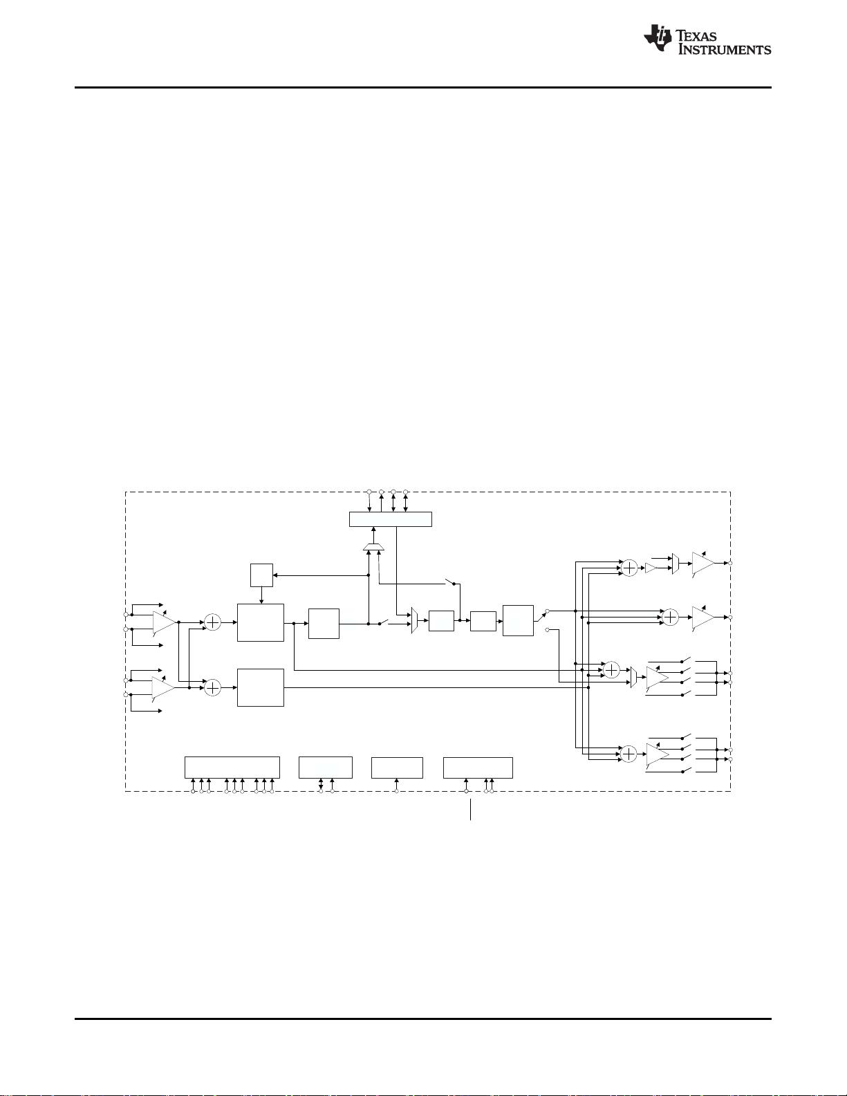
The TLV320AIC3109-Q1 is a highly flexible, low-power, mono audio codec with extensive feature integration
intended for automotive applications. Available in a 5-mm × 5-mm, 32-lead VQFN, the device integrates a host of
features to reduce cost, board space, and power consumption in space-constrained, battery-powered, portable
applications.
The TLV320AIC3109-Q1 consists of the following blocks:
• Mono audio multi-bit, delta-sigma digital-to-analog converter (DAC): 8 kHz–96 kHz
• Mono audio multi-bit, delta-sigma analog-to-digital converter (ADC): 8 kHz–96 kHz
• Programmable gain amplifier (PGA): 0-dB to 59.5-dB gain
• Programmable digital audio effects processing (bass, treble, midrange, EQ, notch filter, de-emphasis)
• Two differential or two single-ended microphone or line inputs
• One differential or two single-ended headphone drivers
• Two fully differential line output drivers
• Fully programmable PLL
• Headphone, headset jack detection available as a register status bit
7.2 Functional Block Diagram

剩余121页未读,继续阅读
2022-12-03 上传
点击了解资源详情
点击了解资源详情
点击了解资源详情
点击了解资源详情
2024-01-23 上传
2024-08-07 上传
2023-04-14 上传

beijixiongyi
- 粉丝: 0
- 资源: 4
 我的内容管理
展开
我的内容管理
展开


最新资源
- AirKiss技术详解:无线传递信息与智能家居连接
- Hibernate主键生成策略详解
- 操作系统实验:位示图法管理磁盘空闲空间
- JSON详解:数据交换的主流格式
- Win7安装Ubuntu双系统详细指南
- FPGA内部结构与工作原理探索
- 信用评分模型解析:WOE、IV与ROC
- 使用LVS+Keepalived构建高可用负载均衡集群
- 微信小程序驱动餐饮与服装业创新转型:便捷管理与低成本优势
- 机器学习入门指南:从基础到进阶
- 解决Win7 IIS配置错误500.22与0x80070032
- SQL-DFS:优化HDFS小文件存储的解决方案
- Hadoop、Hbase、Spark环境部署与主机配置详解
- Kisso:加密会话Cookie实现的单点登录SSO
- OpenCV读取与拼接多幅图像教程
- QT实战:轻松生成与解析JSON数据
