
IEEE
TRANSACTIONS
ON
PATTERN
ANALYSIS
AND
MACHINE
INTELLIGENCE,
VOL.
PAMI-8,
NO.
4,
JULY
1986
w-
I
Lii
(a)
(b)
(c)
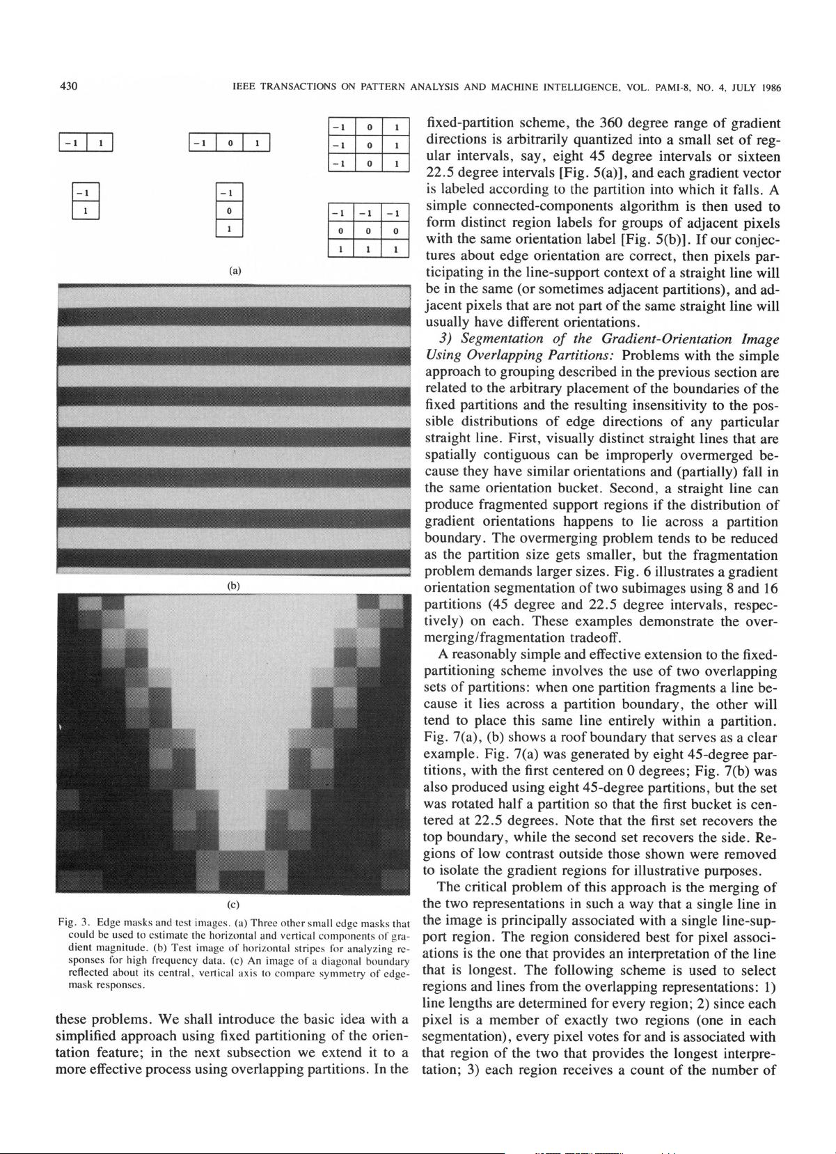
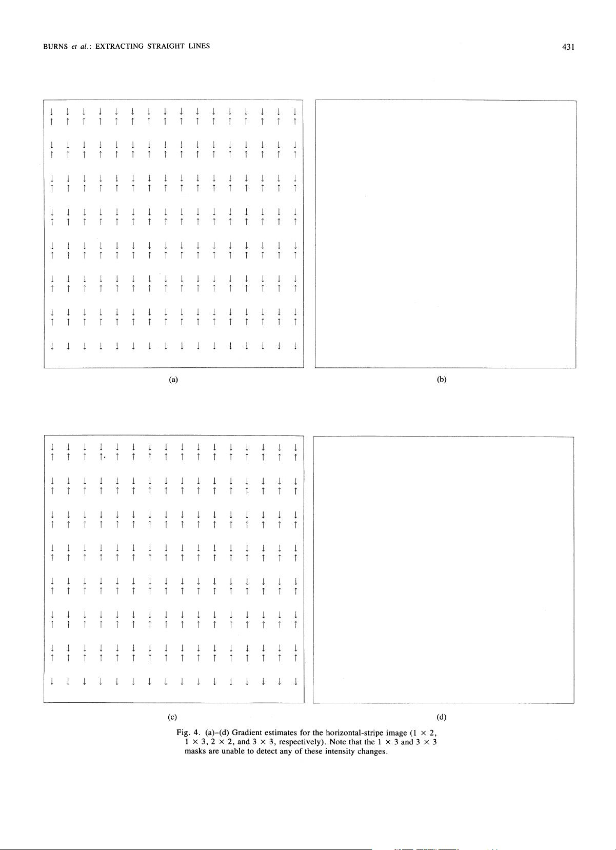
Fig.
3.
Edge
masks
and
test
images.
(a)
Three
other
small
edge
masks
that
could
be
used
to
estimate
the
horizontal
and
vertical
components
of
gra-
dient
magnitude.
(b)
Test
image
of
horizontal
stripes
for
analyzing
re-
sponses
for
high
frequency
data.
(c)
An
image
of
a
diagonal
boundary
reflected
about
its
central,
vertical
axis
to
compare
symmetry
of
edge-
mask
responses.
these
problems.
We
shall
introduce
the
basic
idea
with
a
simplified
approach
using
fixed
partitioning
of
the
orien-
tation
feature;
in
the
next
subsection
we
extend
it
to
a
more
effective
process
using
overlapping
partitions.
In
the
fixed-partition
scheme,
the
360
degree
range
of
gradient
directions
is
arbitrarily
quantized
into
a
small
set
of
reg-
ular
intervals,
say,
eight
45
degree
intervals
or
sixteen
22.5
degree
intervals
[Fig.
5(a)],
and
each
gradient
vector
is
labeled
according
to
the
partition
into
which
it
falls.
A
simple
connected-components
algorithm
is
then
used
to
form
distinct
region
labels
for
groups
of
adjacent
pixels
with
the
same
orientation
label
[Fig.
5(b)].
If
our
conjec-
tures
about
edge
orientation
are
correct,
then
pixels
par-
ticipating
in
the
line-support
context
of
a
straight
line
will
be
in
the
same
(or
sometimes
adjacent
partitions),
and
ad-
jacent
pixels
that
are
not
part
of
the
same
straight
line
will
usually
have
different
orientations.
3)
Segmentation
of
the
Gradient-Orientation
Image
Using
Overlapping
Partitions:
Problems
with
the
simple
approach
to
grouping
described
in
the
previous
section
are
related
to
the
arbitrary
placement
of
the
boundaries
of
the
fixed
partitions
and
the
resulting
insensitivity
to
the
pos-
sible
distributions
of
edge
directions
of
any
particular
straight
line.
First,
visually
distinct
straight
lines
that
are
spatially
contiguous
can
be
improperly
overmerged
be-
cause
they
have
similar
orientations
and
(partially)
fall
in
the
same
orientation
bucket.
Second,
a
straight
line
can
produce
fragmented
support
regions
if
the
distribution
of
gradient
orientations
happens
to
lie
across
a
partition
boundary.
The
overmerging
problem
tends
to
be
reduced
as
the
partition
size
gets
smaller,
but
the
fragmentation
problem
demands
larger
sizes.
Fig.
6
illustrates
a
gradient
orientation
segmentation
of
two
subimages
using
8
and
16
partitions
(45
degree
and
22.5
degree
intervals,
respec-
tively)
on
each.
These
examples
demonstrate
the
over-
merging/fragmentation
tradeoff.
A
reasonably
simple
and
effective
extension
to
the
fixed-
partitioning
scheme
involves
the
use
of
two
overlapping
sets
of
partitions:
when
one
partition
fragments
a
line
be-
cause
it
lies
across
a
partition
boundary,
the
other
will
tend
to
place
this
same
line
entirely
within
a
partition.
Fig.
7(a),
(b)
shows
a
roof
boundary
that
serves
as
a
clear
example.
Fig.
7(a)
was
generated
by
eight
45-degree
par-
titions,
with
the
first
centered
on
0
degrees;
Fig.
7(b)
was
also
produced
using
eight
45-degree
partitions,
but
the
set
was
rotated
half
a
partition
so
that
the
first
bucket
is
cen-
tered
at
22.5
degrees.
Note
that
the
first
set
recovers
the
top
boundary,
while
the
second
set
recovers
the
side.
Re-
gions
of
low
contrast
outside
those
shown
were
removed
to
isolate
the
gradient
regions
for
illustrative
purposes.
The
critical
problem
of
this
approach
is
the
merging
of
the
two
representations
in
such
a
way
that
a
single
line
in
the
image
is
principally
associated
with
a
single
line-sup-
port
region.
The
region
considered
best
for
pixel
associ-
ations
is
the
one
that
provides
an
interpretation
of
the
line
that
is
longest.
The
following
scheme
is
used
to
select
regions
and
lines
from
the
overlapping
representations:
1)
line
lengths
are
determined
for
every
region;
2)
since
each
pixel
is
a
member
of
exactly
two
regions
(one
in
each
segmentation),
every
pixel
votes
for
and
is
associated
with
that
region
of
the
two
that
provides
the
longest
interpre-
tation;
3)
each
region
receives
a
count
of
the
number
of
430
剩余30页未读,继续阅读

O天涯海阁O
- 粉丝: 1552
- 资源: 90
 我的内容管理
收起
我的内容管理
收起
- 我的资源
快来上传第一个资源
 我的收益 登录查看自己的收益
 我的积分
登录查看自己的积分
我的积分
登录查看自己的积分
 我的C币
登录后查看C币余额
我的C币
登录后查看C币余额
 我的收藏
我的收藏  我的下载
我的下载  下载帮助
下载帮助

会员权益专享


最新资源
- 计算机系统基石:深度解析与优化秘籍
- 《ThinkingInJava》中文版:经典Java学习宝典
- 《世界是平的》新版:全球化进程加速与教育挑战
- 编程珠玑:程序员的基础与深度探索
- C# 语言规范4.0详解
- Java编程:兔子繁殖与素数、水仙花数问题探索
- Oracle内存结构详解:SGA与PGA
- Java编程中的经典算法解析
- Logback日志管理系统:从入门到精通
- Maven一站式构建与配置教程:从入门到私服搭建
- Linux TCP/IP网络编程基础与实践
- 《CLR via C# 第3版》- 中文译稿,深度探索.NET框架
- Oracle10gR2 RAC在RedHat上的安装指南
- 微信技术总监解密:从架构设计到敏捷开发
- 民用航空专业英汉对照词典:全面指导航空教学与工作
- Rexroth HVE & HVR 2nd Gen. Power Supply Units应用手册:DIAX04选择与安装指南
资源上传下载、课程学习等过程中有任何疑问或建议,欢迎提出宝贵意见哦~我们会及时处理!
点击此处反馈


