【Practical Exercise】Simulink-Based Modeling of a PID Double-Arm Robotic Hand
发布时间: 2024-09-14 04:50:37 阅读量: 35 订阅数: 22 
# 2.1 The Principle and Design of PID Controllers
### 2.1.1 Structure and Principle of PID Controllers
A PID controller is a type of feedback control system that measures the output of the controlled object, compares it with the desired output, calculates the error, and adjusts the control output based on the proportional, integral, and derivative values of the error. The structure of a PID controller is as follows:
```mermaid
graph LR
subgraph PID Controller
e[Error] --> p[Proportional] --> u[Control Output]
e --> i[Integral] --> u
e --> d[Differential] --> u
end
```
Where:
* e: Error, the difference between the desired and actual output
* p: Proportional coefficient, used to adjust the proportional relationship between the control output and the error
* i: Integral coefficient, used to eliminate steady-state errors
* d: Differential coefficient, used to predict the trend of error changes
The output calculation formula for a PID controller is:
```
u(t) = Kp * e(t) + Ki * ∫e(t)dt + Kd * de(t)/dt
```
Where:
* Kp, Ki, Kd are the proportional, integral, and differential coefficients respectively
* t is the time
# 2. Simulink Modeling of PID Control
### 2.1 PID Controller Principle and Design
#### 2.1.1 Structure and Principle of PID Controllers
A PID controller is a feedback control algorithm used to minimize the error between the system output and the desired output. Its structure is shown in the following diagram:
```mermaid
graph LR
subgraph PID Controller
A[Setpoint] --> B[Error Calculation]
B --> C[Proportional Gain]
B --> D[Integral Gain]
B --> E[Differential Gain]
C --> F[Proportional Term]
D --> G[Integral Term]
E --> H[Differential Term]
F --> I[Output]
G --> I
H --> I
end
```
The error calculation module calculates the error between the setpoint and the actual output. The proportional gain, integral gain, and differential gain modules calculate the proportional, integral, and differential terms, respectively. The output module sums these three terms to obtain the controller's output.
#### 2.1.2 PID Parameter Tuning Methods
The parameters of a PID controller (proportional gain, integral gain, differential gain) ***mon tuning methods include:
***Ziegler-Nichols Method:** Estimates PID parameters based on the parameters of the system's step response curve.
***Cohen-Coon Method:** Calculates PID parameters based on the poles and zeros of the system's transfer function.
***Trial and Error Method:** Optimizes control effects by continuously adjusting PID parameters.
### 2.2 Simulink PID Controller Modeling
#### 2.2.1 Using the PID Controller Module
Simulink provides a PID controller module that makes it easy to implement PID control. The module's inputs include the setpoint, actual output, and parameters (proportional gain, integral gain, differential gain). The output is the controller's output.
```
% Setpoint
ref = 1;
% Actual Output
y = 0.5;
% PID Parameters
Kp = 1;
Ki = 0.1;
Kd = 0.01;
% Create PID Controller Module
pid = pid(Kp, Ki, Kd);
% Calculate Controller Output
u = pid(ref, y);
```
#### 2.2.2 Setting PID Parameters and Simulation
Setting PID parameters requires adjustment according to the characteristics of the system. You can use the trial and error method or other tuning methods to determine the optimal parameters.
```
% Set PID Parameters
pid.Kp = 1;
pid.Ki = 0.1;
pid.Kd = 0.01;
% Simulate PID Controller Response
t = 0:0.1:10;
ref = ones(size(t));
y = zeros(size(t));
for i =
```
 最低0.47元/天 解锁专栏
 送3个月
 百万级
高质量VIP文章无限畅学
百万级
高质量VIP文章无限畅学
 千万级
优质资源任意下载
千万级
优质资源任意下载
 C知道
免费提问 ( 生成式Al产品 )
C知道
免费提问 ( 生成式Al产品 )
0
0
相关推荐

专栏目录
最低0.47元/天 解锁专栏
送3个月
百万级
高质量VIP文章无限畅学
千万级
优质资源任意下载
C知道
免费提问 ( 生成式Al产品 )
最新推荐
Python list remove与列表推导式的内存管理:避免内存泄漏的有效策略
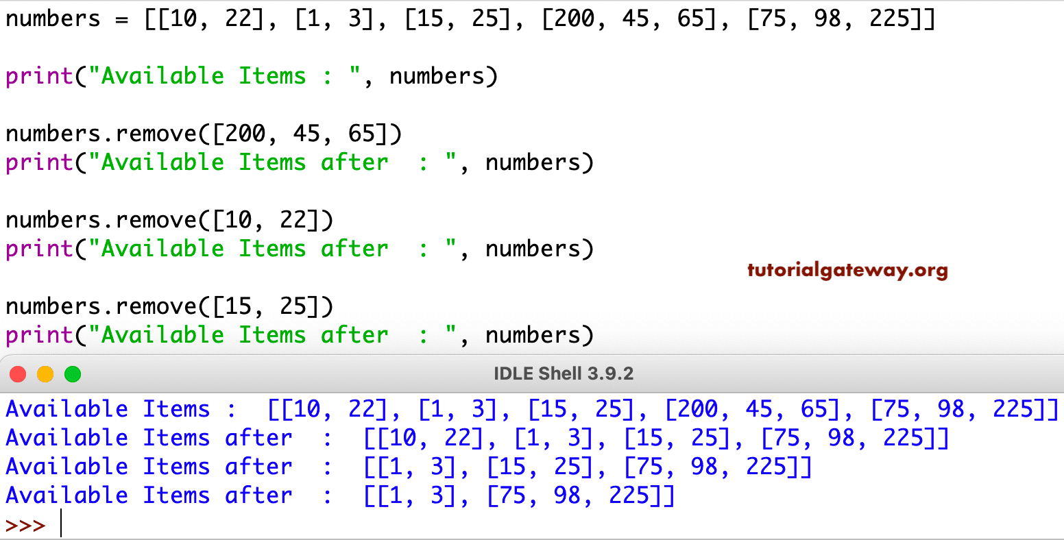
# 1. Python列表基础与内存管理概述
Python作为一门高级编程语言,在内存管理方面提供了众多便捷特性,尤其在处理列表数据结构时,它允许我们以极其简洁的方式进行内存分配与操作。列表是Python中一种基础的数据类型,它是一个可变的、有序的元素集。Python使用动态内存分配来管理列表,这意味着列表的大小可以在运行时根据需要进
Python列表的函数式编程之旅:map和filter让代码更优雅
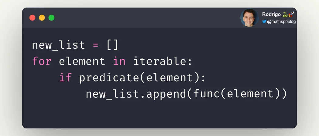
# 1. 函数式编程简介与Python列表基础
## 1.1 函数式编程概述
函数式编程(Functional Programming,FP)是一种编程范式,其主要思想是使用纯函数来构建软件。纯函数是指在相同的输入下总是返回相同输出的函数,并且没有引起任何可观察的副作用。与命令式编程(如C/C++和Java)不同,函数式编程
索引与数据结构选择:如何根据需求选择最佳的Python数据结构
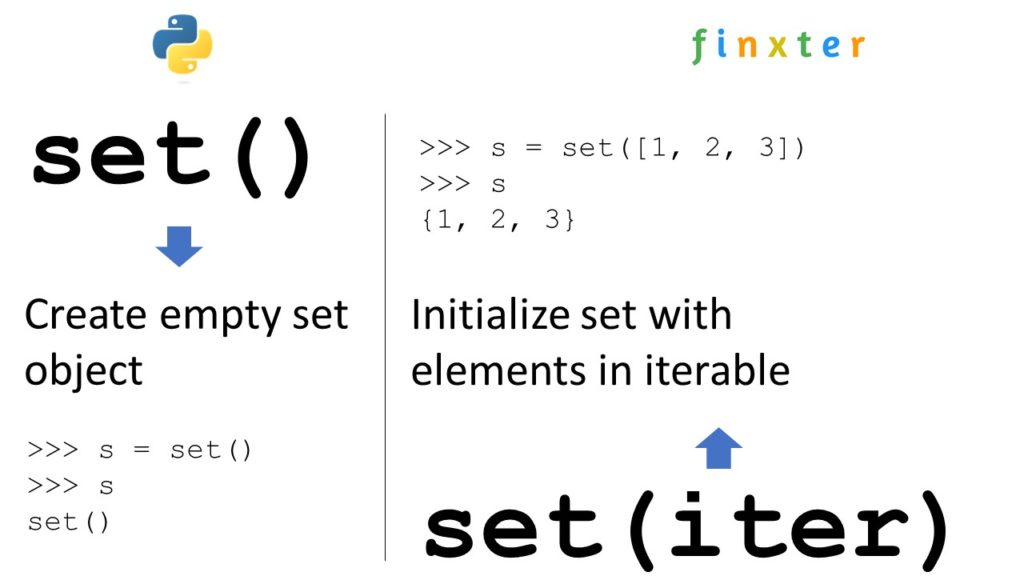
# 1. Python数据结构概述
Python是一种广泛使用的高级编程语言,以其简洁的语法和强大的数据处理能力著称。在进行数据处理、算法设计和软件开发之前,了解Python的核心数据结构是非常必要的。本章将对Python中的数据结构进行一个概览式的介绍,包括基本数据类型、集合类型以及一些高级数据结构。读者通过本章的学习,能够掌握Python数据结构的基本概念,并为进一步深入学习奠
【Python项目管理工具大全】:使用Pipenv和Poetry优化依赖管理

# 1. Python依赖管理的挑战与需求
Python作为一门广泛使用的编程语言,其包管理的便捷性一直是吸引开发者的亮点之一。然而,在依赖管理方面,开发者们面临着各种挑战:从包版本冲突到环境配置复杂性,再到生产环境的精确复现问题。随着项目的增长,这些挑战更是凸显。为了解决这些问题,需求便应运而生——需要一种能够解决版本
Python列表与数据库:列表在数据库操作中的10大应用场景
# 1. Python列表与数据库的交互基础
在当今的数据驱动的应用程序开发中,Python语言凭借其简洁性和强大的库支持,成为处理数据的首选工具之一。数据库作为数据存储的核心,其与Python列表的交互是构建高效数据处理流程的关键。本章我们将从基础开始,深入探讨Python列表与数据库如何协同工作,以及它们交互的基本原理。
## 1.1
【持久化存储】:将内存中的Python字典保存到磁盘的技巧

# 1. 内存与磁盘存储的基本概念
在深入探讨如何使用Python进行数据持久化之前,我们必须先了解内存和磁盘存储的基本概念。计算机系统中的内存指的
Python数据分析与可视化入门:从零开始的数据探索之旅
# 1. Python数据分析与可视化的基础
Python自诞生之初就被设计为一种易于阅读和编写代码的高级语言,随着时间的推移,Python已经成为数据科学领域最流行的语言之一。它的普及主要归功于其强大的库生态系统,其中最知名的是用于数据分析和可视化的Pandas、NumPy、Matplotlib和Seaborn等。数据分析是数据科学的核心组成部分,它涉及数据的收集、处理、分析和可视化,旨在从数据中
Python索引的局限性:当索引不再提高效率时的应对策略

# 1. Python索引的基础知识
在编程世界中,索引是一个至关重要的概念,特别是在处理数组、列表或任何可索引数据结构时。Python中的索引也不例外,它允许我们访问序列中的单个元素、切片、子序列以及其他数据项。理解索引的基础知识,对于编写高效的Python代码至关重要。
## 理解索引的概念
Python中的索引从0开始计数。这意味着列表中的第一个元素
【递归与迭代决策指南】:如何在Python中选择正确的循环类型
# 1. 递归与迭代概念解析
## 1.1 基本定义与区别
递归和迭代是算法设计中常见的两种方法,用于解决可以分解为更小、更相似问题的计算任务。**递归**是一种自引用的方法,通过函数调用自身来解决问题,它将问题简化为规模更小的子问题。而**迭代**则是通过重复应用一系列操作来达到解决问题的目的,通常使用循环结构实现。
## 1.2 应用场景
递归算法在需要进行多级逻辑处理时特别有用,例如树的遍历和分治算法。迭代则在数据集合的处理中更为常见,如排序算法和简单的计数任务。理解这两种方法的区别对于选择最合适的算法至关重要,尤其是在关注性能和资源消耗时。
## 1.3 逻辑结构对比
递归
Python并发控制:在多线程环境中避免竞态条件的策略

# 1. Python并发控制的理论基础
在现代软件开发中,处理并发任务已成为设计高效应用程序的关键因素。Python语言因其简洁易读的语法和强大的库支持,在并发编程领域也表现出色。本章节将为读者介绍并发控制的理论基础,为深入理解和应用Python中的并发工具打下坚实的基础。
## 1.1 并发与并行的概念区分
首先,理解并发和并行之间的区别至关重要。并发(Concurre
资源上传下载、课程学习等过程中有任何疑问或建议,欢迎提出宝贵意见哦~我们会及时处理!
点击此处反馈


专栏目录
最低0.47元/天 解锁专栏
送3个月
百万级
高质量VIP文章无限畅学
千万级
优质资源任意下载
C知道
免费提问 ( 生成式Al产品 )